Howdy Folks,
Seems my off hand comment started some heated discussion about proper heatsinks for this amp. My boy took a look at the KSA 100 case style and thinks it's more cool looking and easier to implement. He also has a line on some 8" x 20" flat back anodized sinks with 48 1" fins on a 3/8 " base. Plans to mount the TO3's on 1/4" thick aluminum 2" x 18" L bolted to the heatsink with some copper sheet and thermal grease between them. Rod's calculator for 50 degrees C heat sink temp and 25 degree C ambient gives a result of .1782 degree C/Watt. Now, is that sufficient to run this amp without a fan? Planning on using TO3's as in the original configuration. Didn't find any real good information in the build wiki. Might be a good time to figure this out and post it up for everone.
My boy has pretty much made up his mind to do it anyway. Kinda stubborn. Can't figure where he got that.
Regards,
Elvin
wiki
Didn't find any real good information about what??? Heatsinking or output TO3 transistors?
geezer1944 said:Howdy Folks,
***
Didn't find any real good information in the build wiki.
***
Regards,
Elvin
Didn't find any real good information about what??? Heatsinking or output TO3 transistors?
Yee-Haww! Got my boards, and Wow are they nice. Thanks again Mark, Al and everyone that contributed, you all really out-did yourselves on the project. Hopefully, you will still be checking in on the thread when us slowpokwes get to the trouble-shooting stage.
Don't think it has gone unnoticed that some of you are already cheating with a "new" project.
Don't think it has gone unnoticed that some of you are already cheating with a "new" project.
Hi Geezer,
the 20 by 8 inch sink that is 3/8inch thick will not dissipate the full heat unless you can distribute your transistors along the 20 dimension.
The reason being that the back plate (3/8inch) can transfer heat effectively over about 10 times the thickness (4inch approx=10*3/8inch). The heat will transfer across the 8inch width from a central device but the extra 12 inches along the the length will be running at a lower temperature and thus only dissipate a lesser amount of heat.
If you can distribute you devices over much of the length then you should be able to achieve the predicted temperatures.
By the way cutting the 20 inch length into two 10 inch lengths will dissipate 40% more heat and almost overcomes the length problem as well.
Howdy AndrewT,
Many thanks for your advice. Your conclusion is the kind of info I was looking for in the build wiki.(apologies to lgreen) Even so, how does one determine the right sink value for the amp regardless of configuration? Maybe some math would be helpful to all the folks out there who are also considering a passive solution.
Idea was to evenly space the four transistors across 18" of the length in the middle of the sink. Hard wire them or maybe make a separate transistor driver board with proper high current/voltage mechanical connectors.
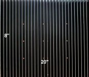
I cut off half of the heatsink pic so's it would fit on this page to show what it looks like. Seems that the fin count my grandson told me is not quite right. There's 60 1" x 8" vertical fins on the thing. I suspect that makes it a bit better for this application.
Regards,
Elvin
Many thanks for your advice. Your conclusion is the kind of info I was looking for in the build wiki.(apologies to lgreen) Even so, how does one determine the right sink value for the amp regardless of configuration? Maybe some math would be helpful to all the folks out there who are also considering a passive solution.
Idea was to evenly space the four transistors across 18" of the length in the middle of the sink. Hard wire them or maybe make a separate transistor driver board with proper high current/voltage mechanical connectors.
I cut off half of the heatsink pic so's it would fit on this page to show what it looks like. Seems that the fin count my grandson told me is not quite right. There's 60 1" x 8" vertical fins on the thing. I suspect that makes it a bit better for this application.
Regards,
Elvin
Attachments
Hi,
you are right, some maths ability is needed to fully design anything including the mechanicals of an amplifier.
I am reluctant to post any spreadsheets to help after receiving considerable criticism, particularly from one of our esteemed designers, for being non intuitive and too complex for our typical contributors.
However there are many web sites with exactly this type of info. ESP and Self come to mind. Application notes can usually be relied on as well. Be thorough with your research and be prepared to dump any info that does not ring true, you must critically evaluate before coming to rely on it.
sink size...
Choosing the 'rating' of a heatsink based on your amps current and voltage parameters is pretty straightforward...
First you decide the idle dissipation for each channel given by the idle current * rail voltage * 2, so for the 'standard', 36v, 1.9A bias we get 36 x 1.9 x 2, or ~140w. Then we need to decide on the 'safe' temperature increase above ambient we can tolerate for the heatsinks. Assuming ambient is 20c, the touch limit is approx. 55c, lower if there are sensitive people that could come into contact. So in this case our increase is ~35c.
Thus the heatsinks we need for each channel need to be rated at 35c/140w, or 0.25c/w
The problem then is easy, we go find/buy a huge chunk of aluminum with tons of fins, the manufacturer will tell us the rating and everyone lives happily ever after...
...Unless you get the sink surplus and don't know the true rating. There are a number of not quite perfect formulas for determining heatsinks ratings, the ones I've tried tend to be unrealistic, so nowaways I oversize by 25% and then adjust the bias to get the temp I want on the surface of the heatsink...
HTH
Stuart
Hi Niles,
Don't worry, I may have had several prototypes, but I spent today drilling and tapping the big heatsink for the new output devices for the final version. I haven't even started on the final chassis yet. So it may seem like we finished ages ago, but it's not true!
You only spotted one?
Don't worry, I may have had several prototypes, but I spent today drilling and tapping the big heatsink for the new output devices for the final version. I haven't even started on the final chassis yet. So it may seem like we finished ages ago, but it's not true!
niles said:Don't think it has gone unnoticed that some of you are already cheating with a "new" project.
You only spotted one?
Howdy Folks and thanks to Stuart Easson,
Ummm, if the Rod Elliott calculator is even close to reliable, then the sink my boy wants to use is .0040 degree C/Watt. Using Mr. Easson's reasoning even with 25% oversize, it should keep him out of trouble.
I am somewhat concerned about hard wireing the TO3's because the length of wire will of necessity be different to the transistors across the 18" span. Maybe want to use a number 10 or 12 ga. wire? A separate driver board could be a good way to keep things neat inside the case. Would a 1 oz. copper board be good enough? Never made an 18" long circuit board before. Sounds like a "challenge" for the young man.
Regards.
Elvin
niles said:Yee-Haww! Got my boards, and Wow are they nice. Thanks again Mark, Al and everyone that contributed, you all really out-did yourselves on the project. Hopefully, you will still be checking in on the thread when us slowpokwes get to the trouble-shooting stage.
Don't think it has gone unnoticed that some of you are already cheating with a "new" project.
HI Niles,
Though I have finished one and am almost finished with the second, I still check in on this thread pretty much everytime I log in. NOt that I can offer much expert advice but I do have some welll earned lumps for the amp and can at least offer some advice baed on experince with it.
I only have one other project started. I promise not to let it consume me.
Blessings, Terry
geezer1944 said:Howdy Folks and thanks to Stuart Easson,
Ummm, if the Rod Elliott calculator is even close to reliable, then the sink my boy wants to use is .0040 degree C/Watt. Using Mr. Easson's reasoning even with 25% oversize, it should keep him out of trouble.
I am somewhat concerned about hard wireing the TO3's because the length of wire will of necessity be different to the transistors across the 18" span. Maybe want to use a number 10 or 12 ga. wire? A separate driver board could be a good way to keep things neat inside the case. Would a 1 oz. copper board be good enough? Never made an 18" long circuit board before. Sounds like a "challenge" for the young man.
Regards.
Elvin
Hi Geezer,
I don't know if you are planning to use sockets but I found that on my first one with the TO3's, I used sockets and both the collectors and the bases were in a straight line and I used a single piece of wire with the insulation removed at each pin, I was able to just solder them. It made for a fairly clean application. You can use a single strand from a 22ga stranded wire to wrap around the heavy wire and pins for a good connection.
The same could be done with the emitter resistors if you have a way of supporting the wire as it runs along beside the TO3's at a great enough distance to fit the resistors. I used 10ga wire for these.
Blessings, Terry
Howdy Terry,
Certainly do intend to use sockets on the TO3's. Something tells me a 16 year old will turn it up real loud and let the magic smoke out!!!!!!!!!!
Found this link which tells me way more math than I probably need. But other folks may find helpfull.
http://homepages.which.net/~paul.hills/Heatsinks/HeatsinksBody.html
Hey all,
I think this is my first post here. Been reading through this thread (very quickly). So sorry if this has been asked to death before.
I have a question - Is the KSA50 that good an amp?
It sounds like it takes a bit of money (as far as diy goes) and a lot of time. For a 20 year old 50W amp? My main reason for asking is that for the price of building one, I can find one on the 2nd hand market, which will save me a lot of time and money. I know it's not as fun as building it yourself. But I just want a good amp, and the only reason I'd make one is if it's much cheaper than buying one, which is not the case with a 2nd hand one.
Your experiences would be appreicated.
Thanks in advanced.
Puunda
Puunda said:Hey all,
***
It sounds like it takes a bit of money (as far as diy goes) and a lot of time. For a 20 year old 50W amp? My main reason for asking is that for the price of building one, I can find one on the 2nd hand market, which will save me a lot of time and money. I know it's not as fun as building it yourself. But I just want a good amp, and the only reason I'd make one is if it's much cheaper than buying one, which is not the case with a 2nd hand one.
***
Puunda
Well, I have enough money to buy one of these relics and not really enough skill to construct one, but somehow through the help of people on this thread, luck, and stubborness I was able to get mine working. I thus feel qualified to answer your question- make one!
Why? Its a lot of fun, you meet good people, and you can make your own modifications- increased output devices, lower/higher bias, etc... For me it was the learning experience and come on, a new DIY you did carefully yourself is better than a 20 year old stock unit....I hope.
Its definately not easy and should not be your 1st project so if you have doubts in this area don't take my advice. But the boards work well (no tweaking needed) and the design is proven so its a great amp for the moderate diyer with sufficient $$ for the critical parts.
Hey "Geezer1944" thanks for the link, your reward is that you and your post are now in the wiki under "heat sinking." Took me long enough to fit you in somewhere.
If you don't like what I said about this, feel free to edit. Haha! no one ever does, that's why I get away with so much. In fact, add your own stuff at will if you find something good. Its anarchy, no one is in charge of that thing.Puunda said:Hey all,
I think this is my first post here. Been reading through this thread (very quickly). So sorry if this has been asked to death before.
I have a question - Is the KSA50 that good an amp?
It sounds like it takes a bit of money (as far as diy goes) and a lot of time. For a 20 year old 50W amp? My main reason for asking is that for the price of building one, I can find one on the 2nd hand market, which will save me a lot of time and money. I know it's not as fun as building it yourself. But I just want a good amp, and the only reason I'd make one is if it's much cheaper than buying one, which is not the case with a 2nd hand one.
Your experiences would be appreicated.
Thanks in advanced.
Puunda
I doubt you could find a good second hand KSA50 for what you can build one for. I don't think this is a difficult amp to build if you use Al's fine boards. It is very forgiving of parts used and I didn't purposfully match any outputs and it works fine. I guess it can get expensive depending how much your heatsinks cost. It does make heat. It's going to be great in my studio this winter.
They've been going for close to a thousand on ebay lately. You can build on for less than half that. If you're not interested in learning then by all means buy a second hand one.
Blessings, Terry
Puunda said:But I just want a good amp, and the only reason I'd make one is if it's much cheaper than buying one
A mint condition original KSA50 will save you a lot of time and will save you money in the long run.
Sell one in 10 years from now and you will make money on the deal.
Building a KSA50 clone will be cheaper, the moment you have other plans and want to sell it you'll loose cash, DIY stuff has next to none re-sale value.
If you build a Krell clone you'll have a better amplifier than the original.
Your homebuilt amplifier will be brandnew, the level of build quality is your choice, and it will outperform a new commercial amplifier that may cost 5 to 6 times as much.
Keep the clone for 10 years and it will be a better investment moneywise than buying something off the shelf.
Some here are considering to clone a Bryston amplifier, a model that costs something like $2500 overhere.
For far less than that amount you can build a Krell clone, even choose to make 2 monaural amplifiers.
The current Bryston 3B SST version i have not heard.
An earlier version Bryston 3B i did have the chance to listen to, as well as an original Krell KSA50.
I have no intention of constructing a Bryston clone.
Difficult choice

- Home
- Amplifiers
- Solid State
- Krell KSA 50 PCB