") Mark.
Mark.Transformer Life
Does anyone know what the life expectancy of a torroid is?
Have seen for sale a pair of second hand high spec British made torroids, 500VA 28-0-28, with single outputs, but they are approximately 10 to 15 years old.
Can anyone comment on their suitability for this project?
They are a reasonable price but I wouldn' want to put the effort into this project and then have the transformers go after a ear or two.
Please advise.
Thanks,
Hugo
Re: Transformer Life
They last absolutely ages, if they are quality.
Since they are British and weren't made in the last 5 years then you can assume quality.
Bud Barnez said:Does anyone know what the life expectancy of a torroid is?
Have seen for sale a pair of second hand high spec British made torroids, 500VA 28-0-28, with single outputs, but they are approximately 10 to 15 years old.
Can anyone comment on their suitability for this project?
They are a reasonable price but I wouldn' want to put the effort into this project and then have the transformers go after a ear or two.
Please advise.
Thanks,
Hugo
They last absolutely ages, if they are quality.
Since they are British and weren't made in the last 5 years then you can assume quality.
case
Worked on my case for 6 hrs yesterday; attaching wood side panels, drilling more holes for ventilation, installing a second fan. I've got a 50 mm fan blowing air in from the bottom and a 120mm fan at the top blowing air out. Man, the mechanical aspects of diy are extremely time consuming.
Hey Terry- hows the case coming?
AndrewT said:Hi Lgreen,
I agree the mech fit out would take me about 4 or 5 times longer than assembling and checking the PCB very carefully.
For me its not just 4-5 times longer than pcbs, throw in a hand wired output stage, soft start circuitry, power supply circuit, and wiring of inputs and outputs, trimming of wires, connectors, and the mech part would still take me about 4 times than all this put together. (Then again, after dropping the input stage maybe it will take some serious debugging time to see if it still works and fix if not...hopefully not)
Plus a mistake on the mech part makes the whole think look stupid, sides not aligned, things not straight. Screw up the front panel and its over. But an electrical mistake can be fixed any number of ways.
I'd rather like 1w versions if the spec is 0.25w to 0.6w unless anyone things they won't fit the PCB.
K-
Troy, I see lots of good info, is this waht you wanted or is there too much info? If the latter, I'd say it's not worth your time to source if from 7 different places, I would not mind paying a little extra if it makes it easy for you, after all you are not getting paid so we should make it easy for you.
Hi,
the small resistors do not have a heat dissipation problem.
The quiescent dissipation for all the resistors from R101 to R130 and all RB & RV are less than 100mW and most are less than 28mW (Vrail=38V).
The exception are the output resistors which see peak dissipations into the Watts range. These are R127 & R128, R204 & R205, all Re.
Have I missed any?
Hi guys,
In an earlier post I asked:
May I assume one main fuse and two per channel, (one for each rail)?
What ratings should be used for each?
Thanks, Terry
In an earlier post I asked:
On another note, I have just about completed my case and will be ready to install everything into it. I've got a question about fuses. How many do I need, what values and where in the circuit should they go?
May I assume one main fuse and two per channel, (one for each rail)?
What ratings should be used for each?
Thanks, Terry
Hi Still4given,
How low do your speakers go?
I recall you said 4ohms, then the DCR will be about 3R and peak current will be about (42-4)/3 = 13Apk. For this I suggest a rail fuse of about F7A 250v.
For a mains fuse start at T5A(240V) or T10A(110v) and reduce it so that it blows at switch on then go back up one size. You may find that T3A250v (240v) or T5A250v (110v) works with a slow start circuit.
Al,
I was not totally happy with your BOM because you subbed in some of the parts values because you had them handy... while thats all find for your project we still would want to keep any parts group buy as true to the original as possible. Except for the current limiting junk Jans list is the most accurate so far for a MK-2 KSA-50 hence I reccomended Jans BOM.
Mark
AndrewT said:Hi,
the small resistors do not have a heat dissipation problem.
The quiescent dissipation for all the resistors from R101 to R130 and all RB & RV are less than 100mW and most are less than 28mW (Vrail=38V).
The exception are the output resistors which see peak dissipations into the Watts range. These are R127 & R128, R204 & R205, all Re.
Have I missed any?
Andrew, my Vrail=80 to 100vdc ;-)
power...
Once the 6ma CCS is in place, none of the front end resistors are power stressed. Without it, the whole front end will die at more than about 60v rails.
Once the front end voltages are held stable the voltage over the rest of the resistors is held quite constant regardless of the supply voltage. Thus the majority of the extra dissipation is in the transistors, and because of this the pre-drivers (q107/108) will need to be heatsunk for complete reliability.
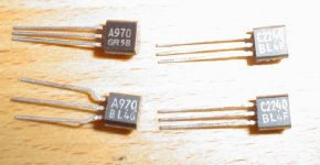
Once the rails are beyond 60v the 2sa970 and 2sc2240 don't have enough Vce to be completely safe, and I substituted the mpsa types for my tests.
Stuart
Once the 6ma CCS is in place, none of the front end resistors are power stressed. Without it, the whole front end will die at more than about 60v rails.
Once the front end voltages are held stable the voltage over the rest of the resistors is held quite constant regardless of the supply voltage. Thus the majority of the extra dissipation is in the transistors, and because of this the pre-drivers (q107/108) will need to be heatsunk for complete reliability.
Once the rails are beyond 60v the 2sa970 and 2sc2240 don't have enough Vce to be completely safe, and I substituted the mpsa types for my tests.
Stuart
- Home
- Amplifiers
- Solid State
- Krell KSA 50 PCB