rabstg said:Coulomb
If your trying to make me paranoid it's working.
")
Actually I am winding you up! Your last several messages make no mention of the Wiki link that you said you would put in every message if nothing else but to drive us nuts.
Regards
Anthony
Hi
It is incredible that there are people in this group who were prepared to do all this work and provide their expertise for free for an unseen group of people they have not seen or met. To me that says a lot for the calibre of people who are members of this audio- community.
I can only convey my deepest felt appreciation for these people who have made this project possible. I would never have even considered tackling a project like this without knowing that somewhere across the world is a group of serious audiophiles who are quietly and without much fanfare building KSA50 clones.
Many thanks to all.
Jozua
Cape Town
South Africa
Some parts?
I've got wiring by the truckload here (well, a couple of 10m spools will be enough, and some high quality OFC rca cabling)
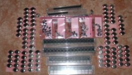
But i've had a few more transistors arrive today Let's just say there's a "pretty penny" worth of transistors here It's to go into 5 channels.... There's another 60 transistors (30 pairs) still on their way, it's to give us some choice for outputs, i'm going for TO-3 21193/94's i think Cut a 94 and 04 (15004?) open and the 94 looks nicer... Maybe a SMALL (i mean microscopic) build difference, the plate the chip is soldered to is smoother with less imperfections
I'm looking for some copper bar stock (about 10ga thickness) for wiring it up, etc... Trying to organise heatsink looks right expensive (1m long piece by 250mm wide with 63mm deep fins) about AUS$150 !! But i'd need 2m for my amp (333Hx500W (that's 2 pieces side by side on 3 panels of the amp))... Should be good for ~250+w (at a low guesstimate, possibly more) per side... So here's my picture so far..... will get a wiring one up tomorrow
Aaron
I've got wiring by the truckload here (well, a couple of 10m spools will be enough, and some high quality OFC rca cabling)
But i've had a few more transistors arrive today
Let's just say there's a "pretty penny" worth of transistors here It's to go into 5 channels.... There's another 60 transistors (30 pairs) still on their way, it's to give us some choice for outputs, i'm going for TO-3 21193/94's i think Cut a 94 and 04 (15004?) open and the 94 looks nicer... Maybe a SMALL (i mean microscopic) build difference, the plate the chip is soldered to is smoother with less imperfections I'm looking for some copper bar stock (about 10ga thickness) for wiring it up, etc... Trying to organise heatsink looks right expensive (1m long piece by 250mm wide with 63mm deep fins) about AUS$150 !! But i'd need 2m for my amp (333Hx500W (that's 2 pieces side by side on 3 panels of the amp))... Should be good for ~250+w (at a low guesstimate, possibly more) per side... So here's my picture so far..... will get a wiring one up tomorrow
Aaron
Attachments
Just a heatsinking question
As a matter of ease (and the fact it's just not made in the size i need), i'm going to use 2x250mmx333mm(h) pieces of heatsink per side of my amp, can i simply use stacks of thermal grease (probably some expensive silver one) to put between the heatsinks and a - say - 4mm-6mm aluminium plate? and screw/bolt them down with a with LOTS of bolts/screws to make sure it holds tight and then have the - say - to-3's bolted to the aluminium plates (off the appropriate alloy brackets, which i can get made easily)... will this work? I'm worried about more metal making conductivity worse or something like that?
It'll just make contstruction 1000% easier
Aaron
A friend sent me this last night and I thought I'd share it. Yes I have build a number of Pass amps and love them!
____________________________________________________
Nelson swiped the sweat of his brow with his forearm.
It was tough cutting through the yellow submarine bulkheads with his
Aleph
torch, but he was seconds away from opening the bulkhead. Finally it
crashed to the floor, revealing a severely damaged mutinous
crewmember, Mark.
Nelson spoke first, "Why, Mark, why would you give up the nirvana of
Pass!!!! Have I not shown you the way to perfect sound bliss?"
Mark grabbed his large X-acto wrench, charging, with the battle yell,
"No
one knows sound nirvana without also experiencing the bass of Krell!"
____________________________________________________
____________________________________________________
Nelson swiped the sweat of his brow with his forearm.
It was tough cutting through the yellow submarine bulkheads with his
Aleph
torch, but he was seconds away from opening the bulkhead. Finally it
crashed to the floor, revealing a severely damaged mutinous
crewmember, Mark.
Nelson spoke first, "Why, Mark, why would you give up the nirvana of
Pass!!!! Have I not shown you the way to perfect sound bliss?"
Mark grabbed his large X-acto wrench, charging, with the battle yell,
"No
one knows sound nirvana without also experiencing the bass of Krell!"
____________________________________________________
Hi Everyone-
I will be placing the order in about 6 hrs...
Get them in quick....
http://www.diyaudio.com/wiki/index.php?page=KSA-50Wiki
I will be placing the order in about 6 hrs...
Get them in quick....
http://www.diyaudio.com/wiki/index.php?page=KSA-50Wiki
All who paid with PayPal-
All paypal receipts came with an address associated with it.
If anyone wants their boards shipped to a DIFFERENT place than their paypal-associated address please email me with the preferred address.
I am printing up shipping labels now and getting the packages ready so when the PCB's arrive I can add x amount in each package and ship out.
Thank you in advance,
Troy
heatsink idea
Farnell.com: 4106003
This has a rating of 0.05 degC/W when force-cooled with a brisk (and probably too noisy) fan - might be worth seeing how it derates with a smaller fan (Papst do one that's rated at 12dB).
Would be a compact and cheap way of getting rid of a lot of heat - also good to arrange for the heat to get blown out of the box rather than using it to bake the capacitors.
I'll try it. I expect sympathy if it goes horribly wrong.
Hi. Just starting on this thread. Just bought two PCB's
I would like to know what is the power supply needed by the amp. transfo rating, voltage. From the real KSA 50 pictures I saw that it is using 2 X 40,000uf caps per channel, it that OK?
Is it necessary to match the outputs transistors that are in parallel?
If yes, it will be pretty expensive to do, these MJ transistors are about 5.83U$ each, ouch
Thanks for your help.
Bye.
I think the original power supply will be fine. Most are thinking that a dual 30 volt secondary 800 watt number will get close to the original. The stock rails were 36 - 37 volt.Algar_emi said:Hi. Just starting on this thread. Just bought two PCB's
I would like to know what is the power supply needed by the amp. transfo rating, voltage. From the real KSA 50 pictures I saw that it is using 2 X 40,000uf caps per channel, it that OK?
Is it necessary to match the outputs transistors that are in parallel?
If yes, it will be pretty expensive to do, these MJ transistors are about 5.83U$ each, ouch
Thanks for your help.
Bye.
In the interest of the best sound the outputs should be matched. There are several options here, but I read that Onsemi will send you 25 samples of each if asked. I purchased mine, the price was 7.50 per 93//94 pair.
My amp is going to be a very low power one, KSA-15 or so. Only one pair of outputs per channel. It also is getting a CLC filter to get the noise low enough for my 100 dB efficient 15 ohm speakers.
For normal speakers, 2 or 3 pair of outputs are needed. The stock power supply should be plenty. This is suposed to be able to drive anything, including the current sucking planars.
George


- Home
- Amplifiers
- Solid State
- Krell KSA 50 PCB