Hey guys I have been reading up on all of these. The Krell I showed is the only populated board version. No trans for any. But antek can supply the simpler ones for the hiraga's. There is also a hi end Marantz clone kit on offer.
For bass the most promising one after contacting jim's audio and asking. He suggested class ab. There is a few different nap 140 kits. This one below at a guess seems the best kit going on parts quality alone. Sanken or Toshiba output trans can be optioned? any advice of the best choice there?
What appeals to me is that it can make 60 or 80 watts from a 24 volt single rail. Its a hi feedback amp so good damping factor. And I have some BIG sla's I can run them off. Naims are known for there rythme. I am currently building a little 23$ naim preamp kit just for fun as it turned out.again battery feed.
eBay Australia: Buy new & used fashion, electronics & home d?r
As for the krell Since no one has any knowledge of this particular kit. I am to scared yet. Or as they say a wise man knows his own limitations or some thing like that. I am definitely building a Hiraga. not sure if it will be the 8 or the 30 yet. I have a pair of 18 0 18 trans which are not quiet suitable for either amp 12v for the 8 watt and 35v for the 30 watt. But the Hiraga will be all out fullrange quality amp. oil signal caps power supply chokes etc. Thanks for you help guys.
Last edited:
Ok I bought two. The cheapest guys are these. I have dealt with them before. He recons they are tested.
YJ KSA50 Class A Mono Amplifier Board New | eBay
YJ KSA50 Class A Mono Amplifier Board New | eBay
Hi Fat,
A pair of 1943/5200 biased to 1.9A shared between them is going to run mighty hot.
Probably too hot for these 150W plastic packaged devices.
Try starting out with a device bias of 100mA and test the amplifier thoroughly.
Increase the bias in 100mA increments after satisfactory 24hrs at the previous bias level.
I suspect you will be OK upto ~500mA device bias, for a total bias of 1A.
This will give ~2Apk of ClassA current into your load.
I've been running my KSA50 now for a while in the nude whilst I am finishing my case. I have been checking the temps regularly and it may seem that I have more heatsink than I bargained for. I am currently running my bias at 325mV per Re. My Re = 0R5. Since I have 3 pairs it gives my Iq = 650mA per pair for a total Iq of 1.95A.
I am measuring temps of 45 degrees C after 2 hours on my sinks at Ta = 22 degrees C. Shall I increase my bias? And to what Iq? As stated previously I am using the MJL1302A/MJL3281A pairs in the TO264 package which is a 200W device. My rail voltages under load is 38.4V. I suspect that I have another 5 degrees C to play with here. I am staring at the datasheets but really have no idea which curve to use as guidance.
I am measuring temps of 45 degrees C after 2 hours on my sinks at Ta = 22 degrees C. Shall I increase my bias? And to what Iq? As stated previously I am using the MJL1302A/MJL3281A pairs in the TO264 package which is a 200W device. My rail voltages under load is 38.4V. I suspect that I have another 5 degrees C to play with here. I am staring at the datasheets but really have no idea which curve to use as guidance.
Hi Henryve,
Since 2 x Iq is peak Class A current, you can presently drive a (~36 / ~4) ohm load -> ~9 ohm to full class A power. if you have a great power supply and the rail voltage doesn't drop as the idle current goes up you can decide when you have enough based on your chosen speakers impedance...I don't think there is much to be gained from more bias than can be used in your driving the speakers (in Class A), but I'm sure many would think there is no such thing as too much.
...and don't forget to allow for whatever ambient temperature extremes apply in your locale.
Stuart
Hi all, glad to see the thread is still running.
I am still playing with the KSA and I am trying to use a seperate supply for the front end up to but not including the drivers. I am using Jans PCB's.
When I use just one supply for the entire channel all is good with the offset showing just a few mV at switch on that falls within a couple of seconds to zero, and when the supply is turned off there is a small rise and then it falls again.
When I use the second supply for the front end the offset at switch on starts at about 500mV and rapidly drops to zero but on switch off the offset hits about 1.9V and takes a very long time to drop to say below 200mV.
The supplies I am using are just rectifier and capacitors, not regulated.
I have tried putting bleed resistors (4.7k) across the caps but not much difference. By the way i am using +-42V for supply voltage
Any suggestions, what am I doing wrong.
Thanks
Alan
Hi Henry ve, thanks for your reply. At the moment I am only experimenting with using a seperate supply for the front end so it consists of a 30-0-30 transformer, two bridge rectifiers and 2 2000uF caps. If it makes an audable difference powering the front end seperatly then I will use a regulated supply.
By the way I forgot to mention that input is grounded and output has no load on it.
I have not yet tried it with music playing, but after the initial turn on period the offset stays very stable and once it has reached operating temp. the bias is also stable.
On a different subject I thought I read a post from Stuart Easson about emiter resistor values and I think he advises that if extra output pairs are used the value should be chosen to equal the original Krell value of 0.5 ohm.eg. the more output pairs the higher the Re should be. Unfortunately I have not been able to find the post again, so I might have dreamt it. Do you know if too many output pairs are detremental to sound quality. The reason I ask is that my heatsinks are drilled for six pairs of TO3's per channel complete overkill I know, but it would fill up all the holes.
Thanks
Alan
Hi Alan,
You did not dream it, and more output transistors with higher Re is good for keeping the gain of the output stage high and the sharing closer to equal.
Your summary is quite correct, if you have twice as many output transistors I'd recommend Re be twice as large, ie the paralleled value of all the Re should match that of the original you are cloning.
HTH
Stuart
Hi,Stuart Easson and Alibear
I'm also thinking to double output transistor amount.
My project based on Jim's PCB and there are 'options' KSA 50 or KSA 100. KSA 50 have one driver (MJE15032,MJE15033) for two (MJ15024,MJ15025) and re 0.5ohm. And KSA100 version the output transistor doubling is done that there are one more driver to other set of output transistor and re 1 ohm.
So my question is if I double my 4 pair (MJ15024,MJ15025) to 8 pairs and change re 1ohm to 2ohm should that modification works? Or should I do drivers something, change type(MJE15034/MJE15035) or something else?
-jussi
Hi Stuart, thanks for the reply. Did you also say that one pair of drivers ( as per Jans PCB) would be OK for the extra output pairs? I think this is the question Jushuota is asking as well.
Also can you see any problems with using a seperate supply for the front end of the amp., Re. my post of a couple of days ago.
Thanks for your help
Alan
Also can you see any problems with using a seperate supply for the front end of the amp., Re. my post of a couple of days ago.
Thanks for your help
Alan
I have been listening to my KSA50 now in the nude for the last 2 weeks. In this time I replaced the Panasonic FC caps in the C102/C103 position with Nichicon KA caps. I have Elna Silmic IIs also but they are just too big for the space provided on the PM boards 
It is funny how a good Class A amp can lay bare how bad some of my old CD's were produced (sound engineering). Some of the U2 recordings are not impressive at all while I was pleasantly surprised by how well the Level 42 recordings were produced.
Now I am moving upstream to sort some of my sources out. Pre-Amp is next in line. Someday I also would like some decent speakers like Martin Logan ribbons.
Damn, my wife is gonna eat me alive as I am also busy with an F5T. And my long term KSA100 project.
I have been listening to my KSA50 now in the nude for the last 2 weeks. In this time I replaced the Panasonic FC caps in the C102/C103 position with Nichicon KA caps. I have Elna Silmic IIs also but they are just too big for the space provided on the PM boards
It is funny how a good Class A amp can lay bare how bad some of my old CD's were produced (sound engineering). Some of the U2 recordings are not impressive at all while I was pleasantly surprised by how well the Level 42 recordings were produced.
Now I am moving upstream to sort some of my sources out. Pre-Amp is next in line. Someday I also would like some decent speakers like Martin Logan ribbons.
Damn, my wife is gonna eat me alive as I am also busy with an F5T. And my long term KSA100 project.
I don't buy that mate. That's actually is discouraging to hear. In my experience with building tube amps the better they get. the lower distortion they are and the more forgiving of source material they become. the more neutral and less colored a amp is the better it will do on poor recordings. It sounds like the ksa 50 amp is not going to be too good full range. How is the bass performance?
I also bought a ten watt zen amp board too for a try at full range. Perhaps it will sound more smoother.
Last edited:
...the more neutral and less colored a amp is the better it will do on poor recordings.
Depends on what you want to hear in a recording.
How is the bass performance?
Stonking!
Very Good I got mine today? Did you use chokes in the power supply's? I am thinking a small hand wound choke coil in a lcr on the output might help with stability. Perhaps it could explain its revealing nature. I notice despite the Chinese Lehman headphone amps having nothing on the output my Altronics version has one for stability. So yea... chokes in the power supply and output might smooth them out beautifully! Of course I wouldn't consider my idea until somebody with some knowledge of ss amps hopefully chimes in and legitimizes my guess work!
Last edited:
I have no Zobel or Thiel network on the output.
I disagree with your point of view. The lesser amount of distortion or colouration an amp adds to the source signal, the more of the actual source signal is amplified and less harmonics added to make the sound either pleasing or horrible to listen to. You know, garbage in, garbage out.
Bass is deep and slamming, but only if there is actual bass in the original recording. You hear this quite well with a recording like Insomnia by Faithless. I must also add that my speakers do sound a bit dry.
Just build the bloody thing alright! Don't let subjective stuff get in the way. It's a good beginner's Class A SS amp to build. This was my very first electronic project that I actually finished and has no vices to catch out a noob.
Chokes in the PS is a good thing in any big PS, although I might add that I believe that the KSA50 has a better PSRR than most other Class A designs.
Last edited:
I have no Zobel or Thiel network on the output.
I disagree with your point of view. The lesser amount of distortion or colouration an amp adds to the source signal, the more of the actual source signal is amplified and less harmonics added to make the sound either pleasing or horrible to listen to. You know, garbage in, garbage out.
Bass is deep and slamming, but only if there is actual bass in the original recording. You hear this quite well with a recording like Insomnia by Faithless. I must also add that my speakers do sound a bit dry.
Just build the bloody thing alright! Don't let subjective stuff get in the way. It's a good beginner's Class A SS amp to build. This was my very first electronic project that I actually finished and has no vices to catch out a noob.
Soon as I can scrounge up the trans. It quiet a expensive power supply with it 2 sets of rails. Thanks for your input buddy. btw My ten watt zen will come first because its going to fit straight into a old 80watt amp chassis that has even the right trans sise and taps and even the heat sinks will fit right. I love it when I can recycle some thing old and crap into something special.
Chokes in the PS is a good thing in any big PS, although I might add that I believe that the KSA50 has a better PSRR than most other Class A designs.
Hi all,I have been constructing a KSA50 for quite some time. The first attemp was using passive cooling and I found it difficult with the heatsinks I was using to succesfuly manage the temperature. I then decided to use fan cooling with two tunnel heatsinks as per original KSA100 amplifier. This was fine, but of course there was the problem of fan noise. I now want to construct a final version of the KSA50 and would really like it passively cooled.Has anyone managed to construct a passively cooled version that was successful and if so could they post pictures or dimensions of their build, not for me to copy, but to point me in the right direction.Any information greatfully received.
Many thanks
Alan.
Many thanks
Alan.
Ali
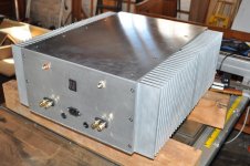
I have my KSA50 running successfully on passive cooling. My heatsinks are on each side as follows:
Depth (front to back of amp) : 508mm
Hight (of amp, whick would be the lenght of the extrusion) : 200mm
Width of my case with the heastinks is 482mm.
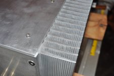
Heatsink Profile info:
Height (Fins + Base ) 76mm
Base : 16 mm
Fins : 60 mm
Fin Distance : 13mm
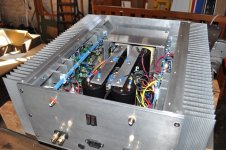
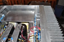
Here are some photos of the amp while in my garage while for final casework. I still need to drill the venting holes and do some finishing, anodising the heatsinks and do final wiring up etc.
I ran the amp for 3 weeks biased at 1.95A and the temperature at Ra = 25 deg C were never higher than 50 deg C.
I have my KSA50 running successfully on passive cooling. My heatsinks are on each side as follows:
Depth (front to back of amp) : 508mm
Hight (of amp, whick would be the lenght of the extrusion) : 200mm
Width of my case with the heastinks is 482mm.
Heatsink Profile info:
Height (Fins + Base ) 76mm
Base : 16 mm
Fins : 60 mm
Fin Distance : 13mm
Here are some photos of the amp while in my garage while for final casework. I still need to drill the venting holes and do some finishing, anodising the heatsinks and do final wiring up etc.
I ran the amp for 3 weeks biased at 1.95A and the temperature at Ra = 25 deg C were never higher than 50 deg C.
Attachments
- Home
- Amplifiers
- Solid State
- Krell KSA 50 PCB