Andrew,
I am thoroughly confused now - please see here...
KSA100s
Shows pics of the KSA100S with 8 pairs output devices. You were even in the posting. Is this not a KSA100s?? It's where I got my pics in my post...
It must be the difference between the KSA100 and KSA100s that is confusing me....could it be the KSA S series has double the output devices than the non S versions??
CORRECTION. My amp has 3 pairs/channel...so as I was saying, at 4ohms, 72 wpc Class A, and at 8 ohms 144 wpc Class A. The 1A per device was correct.
Attachments
Hi,
the Krell info in my post7840 is correct.
That spreadsheet is an easy way to avoid the arithmetic.
But it is flawed. This was pointed out at the time and provided users understood what was needed as input data it gave acceptable results.
I posted a modified version.
the Krell info in my post7840 is correct.
That spreadsheet is an easy way to avoid the arithmetic.
But it is flawed. This was pointed out at the time and provided users understood what was needed as input data it gave acceptable results.
I posted a modified version.
Back to your amp.
3A bias dissipates 234W. That's a lot from 3pair of 150W devices.
Considerably worse than KSA50, which uses 1kW of 200degC devices, whereas your plastic packaged devices are rated to 150degC and 900W.
The amp goes into ClassAB when output current exceeds 6Apk.
So the amp becomes a KSA69 and can push a 4r0 load to 128W.
It cannot drive a 2ohm speaker.
and that 2007 post points out the BIG difference between a 100mk2 and 100s.
Thank you Andrew...I always appreciate your input.
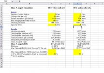
I have made a comparison spreadsheet on all Krells discussed in this thread (I believe I have most of it correct). If anyone knows if values are incorrect we can update the file. I have included mine in the comparison...I think this is the updated spreadsheet Andrew is referring to.
I have made a comparison spreadsheet on all Krells discussed in this thread (I believe I have most of it correct). If anyone knows if values are incorrect we can update the file. I have included mine in the comparison...I think this is the updated spreadsheet Andrew is referring to.
Attachments
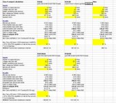
And another more informative spreadheet that adds info on heat sink and Junction temps...again, the listed defualt is my krell conditions. I have Kapton Isolator, .1C/W (methinks) and I really feel the 114 Heatsink temp is accurate on my amp...
Understand I did not author this spreadsheet (someone far smarter than I) as it was original for an Aleph build. I merely modified a few items to use it for the Krell...To whoever wrote the sheet, thanks!
Understand I did not author this spreadsheet (someone far smarter than I) as it was original for an Aleph build. I merely modified a few items to use it for the Krell...To whoever wrote the sheet, thanks!
Attachments
Kapton (0.07) 10times better than mica (0.7)? do more reading.john65b said:And another more informative spreadheet that adds info on heat sink and Junction temps...again, the listed defaalt is my krell conditions. I have Kapton Isolator, .1C/W (methinks) and I really feel the 114 Heatsink temp is accurate on my amp...
krell various uses the wrong formulae in some cells and labels other confusingly.
eg.
Look at "mine".
max ClassA output power is (far) greater than maximum ClassAB power into the same 8r0 load resistance. Nonsense!
I always thought something was fishy there, but never questioned it...
Kapton (0.07) 10times better than mica (0.7)? do more reading.
I was not the author of the spreadsheet...
ksa144.xls is set up for a single ended Class A amplifier and gives the wrong information for a push pull Krell.
It appears to yield same results as the one we have been using on this thread (that appears to be still incorrect), that's why I have been using it - dissipation, wattage, etc. Wouldn't a single ended design be lower power output than PP?
I apologize for causing such confusion...I can ask the moderators to remove my posts if required...
Robby,
é voce fala sobre os disipadores de calor ?
37.5V * 1.8A *2 = 135W de calor o lado, no total 270W para estereo.
Without a fan (ventilador ?) you need a heatsink of 0.20 C/W minimum, or two heatsinks of 0.40 C/W for each channel.
(exemplo : Fischer SK56, 300mm*150mm*40mm, quatro partes para um ampli estereo)
Hello good afternoon to all friends!
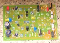
I'm mounting the amplifier Krell 50 and I have a question ... which is connected to where this written LOW! and if so it needs only a tripot from 5k to perfect their operation ... I appreciate everyone's attention!
I'm mounting the amplifier Krell 50 and I have a question ... which is connected to where this written LOW! and if so it needs only a tripot from 5k to perfect their operation ... I appreciate everyone's attention!
Attachments
Hi,
the two connections @ LOW go to a single pole switch or to a SPNO relay.
It gives the option to reduce the Bias to suit warm weather conditions or as a low power standby rather than switch off.
The LOW could be optimum ClassAB and the Normal could be the full ClassA bias.
Another option could be to monitor heatsink temperature and use a relay to switch the amp to a lower ClassA bias to reduce the heatsink temperature, with a warning light to tell you something is wrong.
Be careful to set the two bias pots to work as one adjustment for LOW bias and the other to work in parallel to give the high (normal) adjustment. Check the schematic in case I've got this back to front. This is not on the later PCB, I wish it was.
- Home
- Amplifiers
- Solid State
- Krell KSA 50 PCB