Well, my huge heatsink arrived this morning, so it's slowly coming together. ")
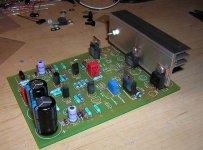
Had another go at the pcb layout as well, it's looking very symetrical now! Bypass caps will all be soldered in the bottom of the PCB, directly to the transistor pins, and to save room, I also went back to just the two higher power resistors for R127/8.
Time to get out the tools, and see how I'm going to mount my T03s to this huge lump of ally...
Attachments
Pinkmouse,
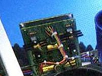
The board looks very good except what I would like to see is R-127 and 128 moved out further so the drivers can be mounted on an adaquate heat sink thats similar to what Krell used on the originals. So far everyones driver sinking leaves ALOT to be desired, its not enough for reliabilitys sake.. The driver semi's run very, very hot. Also I don't know if you will track well thermally with the pre-drivers mounted on the same sink as the drivers. Anyway if you stretched the board longer to accomodate the sink in the photo below as pre the Krell board you will have adaquate cooling plus with the bias transistor mounted dead center between them the thermal tracking is excellent. The pre-drivers run relatuively cool and are fine free air. Yes, these are just suggestions but if you do this and I'll buy a dozen boards from you!
Mark
Attachments
Hmmm........
My predrivers free air hit approx 64deg - with small alu tab they get to about 45....
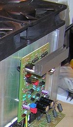
The drivers run "hot" - they stabilise after about 5 hours at a max temp of 62 for one and 58 for the other (not sure of the difference, they are both thermally linked!) bias stabilises after about 5 mins, so that's good......... I'm using 12w/c heatsinks on the alloy link and it's fine...
It IS a tight fit and i have my emitter resistors for the drivers under the board... Works well, looks a *little* messy, but overall i'm happy with the finish as it still looks reasonably professional...
I'm pretty happy with the boards as they are well made and the only thing i think was missed was heatsinking the drivers
Aaron
My predrivers free air hit approx 64deg - with small alu tab they get to about 45....
The drivers run "hot" - they stabilise after about 5 hours at a max temp of 62 for one and 58 for the other (not sure of the difference, they are both thermally linked!) bias stabilises after about 5 mins, so that's good......... I'm using 12w/c heatsinks on the alloy link and it's fine...
It IS a tight fit and i have my emitter resistors for the drivers under the board... Works well, looks a *little* messy, but overall i'm happy with the finish as it still looks reasonably professional...
I'm pretty happy with the boards as they are well made and the only thing i think was missed was heatsinking the drivers
Aaron
Upupa Epops said:Only little notice : shift C 101 little bit to the left - at this position you can't turn by screw of trimpot .
made that mistake too, i had to adjust the pot with pliers.
Keep the comments coming, they are all useful stuff!
I noticed the trimmer as well, that will be tweaked a little, I have the room.
As for the driver heatsinks, how much room should I leave? Is the sink you are using up to the job Mark, or do you think it should be bigger? I put the predrivers on there as well as that is how it seems to be done on the original. I will await all the test results before I change that, as it will need quite a bit of re-routing to implement.
If we do need a bigger heatsink, the idea of putting the emitter resistors on the bottom seems a good one. I would love to increase the size of the board to give a little more space, but I am constrained by the size limitations of the free version of Eagle. If I start using it a lot, I may well go for an upgrade, but I can't afford it at the moment.
As for the earthing, Pavel, that is still under alteration, I think I might have to build a prototype and see how it works - with Eagle, you can get far too buried with little changes and never actually get round to building anything, (why I never use spice!).
Pinkmouse - i do like your board design, very very close to original krell I like the idea that if i want to put SOA protection (doubtful) oneday that it's there ready to go... But i do like your design...
Anyway, here's my latest addition
(it's the final 2 heatsinks - the 3rd channel is running 100% still and sounding excellent!)
Sorry if images slow down the site (?) i can always use the attachment feature or just put a link if there is any complaints (make them if there are!)
It actually took 1 hour (!) on EACH heatsink to drill the holes, on separate days as the drill was FLAT after each one... Then an hour to fit all the parts (and another hour to do all the wiring etc, etc per heatsink next!).... I know why they charge so much for hand-made amps
Aaron
I like the idea that if i want to put SOA protection (doubtful) oneday that it's there ready to go... But i do like your design... Anyway, here's my latest addition
(it's the final 2 heatsinks - the 3rd channel is running 100% still and sounding excellent!)
An externally hosted image should be here but it was not working when we last tested it.
An externally hosted image should be here but it was not working when we last tested it.
Sorry if images slow down the site (?) i can always use the attachment feature or just put a link if there is any complaints (make them if there are!)
It actually took 1 hour (!) on EACH heatsink to drill the holes, on separate days as the drill was FLAT after each one... Then an hour to fit all the parts (and another hour to do all the wiring etc, etc per heatsink next!).... I know why they charge so much for hand-made amps
Aaron
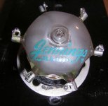
Mark A. Gulbrandsen said:Actually I know of two versions of the heatsink according to pictures I have on hand of various KSA-50's. Most of you have undoubtdly seen the same pictures.... Here they are..... Most likely this is a pre-1983 version......
Hmmm.... notice anything else about it? The board layout is quite (very) different..... The first picture looks like ours, the 'later' one looks like pinkmouses design so far...
They definately look quite different... maybe to accomodate the single heatsink?
Aaron
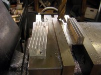
My version.... the fins are tad bit smaller and it is as wide as the pcb is. With the fins pointing up allowing heat to rise it should be at least as good as the original Krell's driver sink. Its just not that beautiful Martha Stewart Blue yet thet the Dan man seems to love so much.....
Mark
Mark
Attachments
NUTTTR,
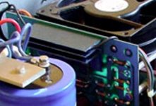
Yes, very different! I prefer the later versionwith room for that larger heat sink. BTW: That large sink is very easy to make up! While I do have daily access to a vert. mill anyone can get a sink like this and cut off some of the fins with a hacksaw and then draw file that area flat to mount the TO-220's onto..... very easy either way...... Mine started out as a 50 cent surplus sink like on the left. Another thought is to mount the drivers off the board onto the main heat sink..... no real reason not to.... many power amps have their drivers mounted with the output devices.
Glad you have yours up and running!! I made a change to my bridge and cap assy. last night which places the bridge right on the caps as Krell did with theirs...... The really off thing is that it soulds ALOT better than it did with the bridge seperately mounted further away. I did this just to keep things more compact as I plan on making it completely dual mono. I can't explain the difference in sound though.....
Elso, I was re-posting that photo after further Photoshopping to enhance it.... you must have caught in while I was changing it!!
Mark
Attachments
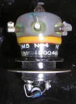
On another note I bought some neato Vacuum relays the other day for 5 bucks surplus. These babies are about1" O.D. and 2 inches long. They are rated at 30kv and 15 amps with ukltra low contact resistance at in the low .01 range at ultra high frequencies... One can assume these would be just as good at audiop frequencies so I may gove them a try as output relays in the 50. can anyone here shed any more light on these things?
Attachments
- Home
- Amplifiers
- Solid State
- Krell KSA 50 PCB