NUTTTR said:Hmmm...
Will i need a heatsink on the bias transistor? (i'm mounting it to the mainboard not the main heatsinks...)??
Aaron
I think the Bias Transistor has to be thermally coupled to the output devices to track properly?
Regards
Anthony
the bias transistor...
...should only have a maximum of 4 or 5 volts under even the most heavily biased conditions, so I don't think it will need it's own heatsink per se. It is often mounted on the same heatsink as either the outputs or the drivers, to provide some thermal compensation. As temperatures rise, everything heats up and the overall bias voltage needs to decrease at a similar rate to the decreasing forward bias voltage of the output transistors.
Anthony, I don't think my ebay details are any more at risk in the hands of the auction sniper folks than they are in the hands of the ebay people, and arguably ebay is a much more likely target for hackers...Auction sniper makes ebay significantly more functional for me, with much less wasted time, so at this point it seems like a worthwhile exposure...
Stuart
Re: the bias transistor...
Well yeah, but it is sort of like hunting rabbit with a Vulcan MKII Cannon!")
Anrthony
Stuart Easson said:...should only have a maximum of 4 or 5 volts under even the most heavily biased conditions, so I don't think it will need it's own heatsink per se. It is often mounted on the same heatsink as either the outputs or the drivers, to provide some thermal compensation. As temperatures rise, everything heats up and the overall bias voltage needs to decrease at a similar rate to the decreasing forward bias voltage of the output transistors.
Anthony, I don't think my ebay details are any more at risk in the hands of the auction sniper folks than they are in the hands of the ebay people, and arguably ebay is a much more likely target for hackers...Auction sniper makes ebay significantly more functional for me, with much less wasted time, so at this point it seems like a worthwhile exposure...
Stuart
Well yeah, but it is sort of like hunting rabbit with a Vulcan MKII Cannon!
Anrthony
funny you should mention....
hunting rabbit...
was just trading amp war stories with ace, I had a friend with a pet rabbit that ate a set of input and speaker cables, the amp and rabbit survived. The next time however he headed straight for the power cable, neither survived...
So which protection circuit is appropriate? Just how big a fuse do you need to make sure the rabbit is properly cooked, medium rare?
Stuart
Re: funny you should mention....
Poor Rabbit
Well my Mum is from Malta, where they raised rabbits in the house as a food source. We had been living in Canada for some years and become well aquainted with the nieghbours at the time. They were going on vacation and asked us to feed thier pet rabbits which were in an outdoor pen for the summer, my Dad said sure, not a problem. Well my Mum figures they will not miss a rabbit and she will replace it next time she goes to the butcher. So she grabs one, slaughters it and makes rabbit stew for dinner. My dad compliments my Mum on the stew as we all did, and asks what meat did she use. Well Fresh Rabbit of course was the response, where did you get Fresh Rabbit my dad asks, Mum does not drive, from next door she say's. We were all sick, my Mum you see just thinks of them as food and assumed the nieghbours did as well, after all they had half a dozen of them.
When the nieghbours returned and the kids went to visit thier fluffy bunnies, it did not take long for one of the kids to start crying where's whats it's name! Well yadda yadda yadda, the nieghbours never spoke to us again and to this day I can no longer eat rabbit or anything else that could be a pet for that matter.
True Story
Anthony
Stuart Easson said:hunting rabbit...
was just trading amp war stories with ace, I had a friend with a pet rabbit that ate a set of input and speaker cables, the amp and rabbit survived. The next time however he headed straight for the power cable, neither survived...
So which protection circuit is appropriate? Just how big a fuse do you need to make sure the rabbit is properly cooked, medium rare?
Stuart
Poor Rabbit
Well my Mum is from Malta, where they raised rabbits in the house as a food source. We had been living in Canada for some years and become well aquainted with the nieghbours at the time. They were going on vacation and asked us to feed thier pet rabbits which were in an outdoor pen for the summer, my Dad said sure, not a problem. Well my Mum figures they will not miss a rabbit and she will replace it next time she goes to the butcher. So she grabs one, slaughters it and makes rabbit stew for dinner. My dad compliments my Mum on the stew as we all did, and asks what meat did she use. Well Fresh Rabbit of course was the response, where did you get Fresh Rabbit my dad asks, Mum does not drive, from next door she say's. We were all sick, my Mum you see just thinks of them as food and assumed the nieghbours did as well, after all they had half a dozen of them.
When the nieghbours returned and the kids went to visit thier fluffy bunnies, it did not take long for one of the kids to start crying where's whats it's name! Well yadda yadda yadda, the nieghbours never spoke to us again and to this day I can no longer eat rabbit or anything else that could be a pet for that matter.
True Story
Anthony
I figured that Krell didn't have the bias transistor on the main heatsinks in any but the very first class a KSA-50's, so i'd keep it onboard... but with a separate heatsink, i mean, it's temp will be fairly constant... i'm going to bias it according to ambient temp... i would have thought this would be ok?Later krell's bias is on the same heatsink as the drivers... Should i bother? Being class A the bias really doesn't change that much, even if it does get hotter, maybe a bit, but if it gets to that point, i'd prefer the bias chip to be unheatsunk and get hot prematurely and lower the bias which will also keep ambient temp down... does that sound feasable?
Otherwise i can remove it from my boards and hardwire to the heatsink?
Aaron
Otherwise i can remove it from my boards and hardwire to the heatsink?
Aaron
true enough, but...
...one day you may decide to use the awesome class B capabilities of the amp, after all we are building it for it's welding as well as sonic capabilities. At this point you will want the bias transistor mounted somewhere that has a temperature proportionally related to the output level of the amp...
Traditionally it's put on the output heatsink, but I think probably that attaching it to one of the drivers is good too. For most purposes it probably isn't necessary, but I figure it's easy enough to do.
Stuart
...more...
The bias transistor is unlikely to get hot due to it's internal dissipation, the idea is it is made hot by the heat dissipated in the output stage. Since it is a VBE multiplier, as it warms and it's Vbe drops, the total bias voltage drops, and the quiescent current drops.
Yet another form of negative feedback, just a little slower than the one we normally talk about...
Stuart
"Should i bother? Being class A the bias really doesn't change that much, even if it does get hotter, maybe a bit, but if it gets to that point, i'd prefer the bias chip to be unheatsunk and get hot prematurely and lower the bias which will also keep ambient temp down... "
I am locating mine on the driver heat sink. I am making a one piece sink just like the original has on the drivers. If you don't allow it to track something that is temperature related to the output stage than you also face the risk of thermal runaway in which the output devices will literally melt down their junctions.
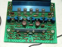
When you bias the amp let it heat up over time, monitor and tweek the bias till its at the point you want at its operating temp. With the bias mounted along side the drivers the bias transistor has a definate temperture to sense and should keep the amp in class A at your preset point and track the overall temperature so it doesn't go over your preset bias point. If you allow it to stand free air then there is nothing for the transistor to sense but the free air temp and then'll be much lower that the rest of the amp and probably no relation at all to what the devices are doing. The output stage may just keep getting hotter and hotter and melt down...... this has always been a problem with bi-polor silicon output devices. In the photo the blue heatsink at the top has the drivers on it and the bias transistor.
Mark
I am locating mine on the driver heat sink. I am making a one piece sink just like the original has on the drivers. If you don't allow it to track something that is temperature related to the output stage than you also face the risk of thermal runaway in which the output devices will literally melt down their junctions.
When you bias the amp let it heat up over time, monitor and tweek the bias till its at the point you want at its operating temp. With the bias mounted along side the drivers the bias transistor has a definate temperture to sense and should keep the amp in class A at your preset point and track the overall temperature so it doesn't go over your preset bias point. If you allow it to stand free air then there is nothing for the transistor to sense but the free air temp and then'll be much lower that the rest of the amp and probably no relation at all to what the devices are doing. The output stage may just keep getting hotter and hotter and melt down...... this has always been a problem with bi-polor silicon output devices. In the photo the blue heatsink at the top has the drivers on it and the bias transistor.
Mark
Attachments
I can always use a piece of copper sheet to "join" the 2 main drivers together and just attach the bias trans to that... that'd work.... i notice that the krell has all the drivers heatsinked, however in our diagrams, etc it only states the main 2 needing heatsinks... I was only planning on heatsinking the main 2 (and now) the bias transistor...
I was planning on just using a strip (about 2-3cm wide) bolted directly on the back of the TO-220 drivers and then have the heatsinks bolted to that.... that was my plan... what is everyone else doing?!
I was planning on just using a strip (about 2-3cm wide) bolted directly on the back of the TO-220 drivers and then have the heatsinks bolted to that.... that was my plan... what is everyone else doing?!
NUTTR,
The copper strip is a good choice as it conducts heat very quickly allowing the bias transistor to track even better. I am fashioning mine from a scrap of copper bar that I am going to machine.... the backs of the driver transistors are at opposite sides! So the heat sink has to be machined with a jog at each end so that it still lies straight across and looks good. BTW: Having a silver flash plating over the copper raises the efficiency of a copper heat sink dramatically! Good luck with yours, its a good choice of material.
Mark
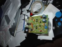
I managed to get some alum strip today, might use that instead, for a particular reason, it's cheap and quite thin so will conduct heat pretty well (it's about 1mm thick!) and i have little clip things i can use to hold the bias transistor to it, so that should work OK... i think... Now i have to isolate it all!! I am going to be sanding the alloy very very smooth and potentially a little thinner, depending on how rough the surface ends up appearing
Copper bar, etc isn't as easy to get as i thought, i will have to ring around during the week if i go that way!
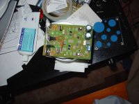
I'd mount the bias to the main heatsink, but having fans and being large it's going to take quite a while to get hot... whereas the drivers, etc will get hot a lot faster on smaller heatsinks and no fans... I don't mind running wires, etc but i'm trying to keep the boards as compact as possible
Aaron
Copper bar, etc isn't as easy to get as i thought, i will have to ring around during the week if i go that way!
I'd mount the bias to the main heatsink, but having fans and being large it's going to take quite a while to get hot... whereas the drivers, etc will get hot a lot faster on smaller heatsinks and no fans... I don't mind running wires, etc but i'm trying to keep the boards as compact as possible
Aaron
Last one!
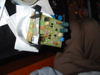
I've got the other 4 boards to do in the same way now *shudders*... Thermal paste makes a massive mess, i used as little as possible, but i ended up spreading it everywhere!!!
Aaron
[edit - i'm not using the SOA protection at all, that's how i can waste most of that space with leads, etc]
I've got the other 4 boards to do in the same way now *shudders*... Thermal paste makes a massive mess, i used as little as possible, but i ended up spreading it everywhere!!!
Aaron
[edit - i'm not using the SOA protection at all, that's how i can waste most of that space with leads, etc
]Attachments
A thought...
I know due to matching, etc that one driver will most likely be hotter than the other - but instead of joining both with the alum/copper/whatever can we "hook" the bias transistor to one heatsink of one driver alone? I mean, wouldn't both the drivers increase temp at a similar rate... so that could make my "mess" a lot neater
How's everyone else going with their boards?
Coulomb said:Hello Stuart, is there a chart or spread sheet to show the resistors and thier values that effect the output power and mode?
I am using a 30-0-30 VAC transformer and I would like the first 30% output class A and the slip to A/B above that.
I have found the bouncing around of what seems like misinformation on this thread very confusing. Maybe I just have too many amps under construction!
Regards
Anthony
Email me and I will send you an excel sheet I made for Class-A calcs. Chocoholic, Eva and Nelson helped me with it...
another method for mounting bias tranny...
If you bolt a 3"x1/2"x1/8" (3mm) piece of Al, or Cu to the fronts of the respective tabs, it runs between the 2 transistors quite nicely, one in front and one behind. The heatsinks bolt on the back o' the tab as usual, and the bias transistor bolts to the bar in between...As a convenient extra it also sits high enough above the board to allow the I/V limiter to still be present for them as want it.
Just have to add resistors to the boards then connect it to some power and I can start destroying components...
Stuart
- Home
- Amplifiers
- Solid State
- Krell KSA 50 PCB