Re: more of everything...
Thank you for the input, I'm proceeding.
As Mr. T pointed out to me, with dual drivers in the 100 design, you can only have outputs in multiples of two. I was dead set on 5 pairs until it was noted to me. 2, 4, 6, 8...but you may know this and I'm pointing out the obvoius?
Thanks a bunch,
Shawn.
Stuart Easson said:OTOH If I get lazy about drilling all the darn holes, instead of 4 x TO3 pairs I may go for 5 or 6 pairs of the plastic outputs (mj21193/4).
Stuart
Thank you for the input, I'm proceeding.
As Mr. T pointed out to me, with dual drivers in the 100 design, you can only have outputs in multiples of two. I was dead set on 5 pairs until it was noted to me. 2, 4, 6, 8...but you may know this and I'm pointing out the obvoius?
Thanks a bunch,
Shawn.
Your lineup should be fine. I used 15003/4 on the protoypes then 211193/4s on my final version. They did sound slightly different, but it was minor, one set was not better than another, just different. I can't even really put it into words that well. I'll never make a hifi journalist ")
Pink preference
But which ones did you like better or can you actually pin it down. I won't get into semantics with you as I am not well in that department either.
BTW Mr. Mouse these boards are wonderful. I was out on the town today showing them off. Some of the parts suppliers couldn't even grasp the concept of what takes place here on the forums and around the world with DIY Audio.
Shawn.
pinkmouse said:Your lineup should be fine. I used 15003/4 on the protoypes then 211193/4s on my final version. They did sound slightly different, but ...
But which ones did you like better or can you actually pin it down. I won't get into semantics with you as I am not well in that department either.
BTW Mr. Mouse these boards are wonderful. I was out on the town today showing them off. Some of the parts suppliers couldn't even grasp the concept of what takes place here on the forums and around the world with DIY Audio.
Shawn.
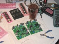
HI TomWaits
It look like those pc boards what you purchased from me .Looking nice .I'm not going to finish my KSA-50 even I have all the parts , transformer etc .I will put together the KSA-100 when the boards will be ready .
May be later I will sell my populated pc boards with the Plitron 2x30V 1KVA transformer together .
Please let me know the result after you tested .
Just be careful with the glass it may catch fire .
Regards
Yes my friend! Thanks and remember who owes you 5$!gaborbela said:HI TomWaits
It look like those pc boards what you purchased from me .Looking nice.
That is too bad but your money would come back to you if you sell and that's a good thing. You to are a man of many projects...who has the time to finish them all?
I'm not going to finish my KSA-50 even I have all the parts , transformer etc .I will put together the KSA-100 when the boards will be ready .May be later I will sell my populated pc boards with the Plitron 2x30V 1KVA transformer together .
Please let me know the result after you tested .Just be careful with the glass it may catch fire .
????
Glass? Fire? Please don't tell the fire department. I'll post many details, heck I'll need my own thread the way I go on with things. This is a shared topic perhaps I should tone it down a bit as I tend to stretch alot...Thanks Gabor,
Shawn.
K-amps said:Tom sorry for not cathing your post earlier... IMHO 15034/5 sound better than 30/31. Perhaps better gain has something to do with it... maybe not...
Oh well, they are in the PCB and the beer has run out. Time for a nap...
Cheers,
Shawn.
Long time no post around this!!!
I should have posted sooner, but I haven't touched the amp in a long time, just been enjoying the sound
Well, currently i'm 'rebuilding' the amp... Not the amp as such, more the 'frame' that it is on. I'm building a proper frame for it so that I can raise it off the floor and maybe make a case for it - Maybe some nice timber, maybe polished alloy... Maybe both? Not sure yet. I can post pic's later tonight or tomorrow, depending on my progress, but as some may remember my amp is a little overspec
Aaron
Re: Pink preference
It gets even more complicated! I'm now using MJE3821/1302, which definitely sound better, but I still haven't actually finished the case yet with that one, I need to buy some copper sheet and I just haven't had the spare cash in the last few months.
Thanks. I agree, diyAudio is a wonderful resource, but the real thanks need to go to all the people who just kept hassling me to do it right and taught me how.
Aaron, welcome back! Com'on, you know you need to post pics!
TomWaits said:But which ones did you like better or can you actually pin it down?
It gets even more complicated! I'm now using MJE3821/1302, which definitely sound better, but I still haven't actually finished the case yet with that one, I need to buy some copper sheet and I just haven't had the spare cash in the last few months.
BTW Mr. Mouse these boards are wonderful. ...Some of the parts suppliers couldn't even grasp the concept of what takes place here on the forums and around the world with DIY Audio.
Thanks. I agree, diyAudio is a wonderful resource, but the real thanks need to go to all the people who just kept hassling me to do it right and taught me how.
Aaron, welcome back! Com'on, you know you need to post pics!
Bit of a run down:
This amp does ~ 130w RMS class A into 4 ohms (Yes, that's 130w/channel), at 4 ohms it runs into A/B before running out of RMS, however on 8 ohm, it is 100% class A the whole way
The 'tab' heatsinks on the boards will be replaced with proper small heatsinks sometime soon... (the drivers themselves are mounted on the main heatsink body)
So, one toroid is sitting there waiting to be mounted, it's 6.*" diameter, 800va, those heatsinks are 350mm long, there's 4 fans (8cm) underneath. The frame is all alloy square tubing and is VERY strong (20kg and it doesn't flex). The base plate is 6mm MDF at the moment, but it will be 3mm alloy plate (MDF is a template).
The next step is more drilling (need a new drill bit) and then I am building a 12v circuit for powering the fan (which can be switched between 7.5v output and 10v output for the summer). This will also power a pair of 30amp 240 relays so if fan power dies, then the amp power gets cut off too!
Anway, if the pics don't work, just right click them and click 'show picture'...as my server isn't working properly at the moment...
Hope that's a nice 'teaser'...
Yes, it is a big amp (500mmx575mm base!!!)
Aaron
This amp does ~ 130w RMS class A into 4 ohms (Yes, that's 130w/channel), at 4 ohms it runs into A/B before running out of RMS, however on 8 ohm, it is 100% class A the whole way
The 'tab' heatsinks on the boards will be replaced with proper small heatsinks sometime soon... (the drivers themselves are mounted on the main heatsink body)
So, one toroid is sitting there waiting to be mounted, it's 6.*" diameter, 800va, those heatsinks are 350mm long, there's 4 fans (8cm) underneath. The frame is all alloy square tubing and is VERY strong (20kg and it doesn't flex). The base plate is 6mm MDF at the moment, but it will be 3mm alloy plate (MDF is a template).
The next step is more drilling (need a new drill bit) and then I am building a 12v circuit for powering the fan (which can be switched between 7.5v output and 10v output for the summer). This will also power a pair of 30amp 240 relays so if fan power dies, then the amp power gets cut off too!
Anway, if the pics don't work, just right click them and click 'show picture'...as my server isn't working properly at the moment...
An externally hosted image should be here but it was not working when we last tested it.
An externally hosted image should be here but it was not working when we last tested it.
An externally hosted image should be here but it was not working when we last tested it.
Hope that's a nice 'teaser'...
Yes, it is a big amp (500mmx575mm base!!!)
Aaron
K-amps said:Holy! 10 OP devices per channel??
Those caps seem small compared to the rest even though they are 68mf
hehehe

Yes... I've got a watt meter on the amp too
Drains a LOT of power (at idle). When cranking it LOUD, it actually cools down!!! (more power to the speaker than the output devices)...Aaron
Ah, the plummers amp. Looking forward to seeing it!It gets even more complicated! I'm now using MJE3821/1302, which definitely sound better, but I still haven't actually finished the case yet with that one, I need to buy some copper sheet and I just haven't had the spare cash in the last few months.
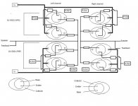
Guys, some months back I posted this schematic or what to call it and got it confirmed as correct. However, when looking at the datasheet from onsemi, page 3, I think I have reversed the Base and Emitterpins.
When comparing my drawing to the datasheet and seeing the transistors from above and pins situated on the bottonside, is it still correct?
When comparing my drawing to the datasheet and seeing the transistors from above and pins situated on the bottonside, is it still correct?
Attachments

Originally posted by K-amps
Holy! 10 OP devices per channel??
NUTTTR said:
hehehe
Yes... I've got a watt meter on the amp too
Aaron
Yeah, I've got 8 output devices per channel and also notice that the amp cools down when you drive it hard.
FYI, I've added KMJ's amp to my web site under "guest pages" (I'm pretty sure he gave me permission for this). Its kind of rough now but I'm going to add more...I hope. If any of you would like, please email me and we can put your krell up there too; I will add the witty commentary for free!
keep up the good work
kmj said:Guys, some months back I posted this schematic or what to call it and got it confirmed as correct. However, when looking at the datasheet from onsemi, page 3, I think I have reversed the Base and Emitterpins.
When comparing my drawing to the datasheet and seeing the transistors from above and pins situated on the bottonside, is it still correct?
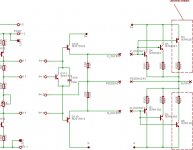
I see a lot of Pout and no in. Typo?
You intend to use resitors on the base of each output TO3. I have thought the PinkMouse and krell designs did not use the base resitors? I did however see them in Jan's work.
Is this a preference or has to do with something else? I'm making my layout right now for my TO-3's with one NPN and one PNP per heat sink per output board, so I am wondering if I was about to do something wrong.
Also, there are two 1N4004's on the back end of the old Krell Schematic but they are not present on the one attached. Do I need these diodes? If so, where should I locate them if I have 3 TO-3 boards per channel with a comp. pair on each.
Attachments
- Home
- Amplifiers
- Solid State
- Krell KSA 50 PCB