Hi Greg,
have another look at ESP's grounding. The diagram shows four separated grounds spread between the two central capacitors (speaker returns and signal grounds). This is clearly poor grounding practice.
I think you are referring to something else namely combining the dirty, power and signal grounds. Many views are held on this or using the resistor separation philosophy. I prefer the resistor separation but I did give Still4given the alternatives to let him choose/experiment for himself.
Could you clarify which camp you are in;- ESP's diagram is either right or wrong? grounds should minimise voltage differences across the reference points or grounds can be located at any varying voltage and to h..l with the deleterious effects on sound quality.
still4given said:The fan I bought today can be seen here.
At 49cfm and a circular passage of 4.59" airspeed is in the order or 7 feet/sec for this one.
7 ft/sec will about halve the thermal resistance of your heatsink assembly.
With the estimate for your duct with esp's heatsink.zip that should give you an easy estimate on the temperature of your megadome.
Looks like a very nice fan to me, Terry, you Vet-Rocker you.
(is that an Ovation guitar in the corner of your livingroom?)
Hi guys,
OK, I'm a dope. Thanks goodness I had the safety resistors installed and was using a variac. I did a real newbee move and had installed the outputs backwards, I had the PNP, NPN reversed. I thought I had douple checked that but somehow I guess I didn't. Fortunately, I had used sockets so it was fairly easy to change them. Things are looking better now. It was very late when I finished swapping things so I haven't had a chance to do much more than a quick check of the voltages. I will let you know more sometime this morning.
I did do the mods on the boards.
Thanks for all of your help.
jacco,
Yep, an Ovation. You have good eyes.
Blessings, Terry
Yep, an Ovation. You have good eyes.
Yes but is it standing in the corner?
Anthony
We all want a little applause in life.
Nahh, not quite, at least Pabst offers reliable datasheets. Anything below 25 db is fine.
Magura,
Measured how? Weighted A,B,C, or no weighting, at what distance? Anechoic chamber or any old place?
I can't believe all the time wasted on the AC fan stuuff when with 30 min. of circuit building he could have had a nice quiet running DC fan
.Mark
Mark A. Gulbrandsen said:
Magura,
Measured how? Weighted A,B,C, or no weighting, at what distance? Anechoic chamber or any old place?
I can't believe all the time wasted on the AC fan stuuff when with 30 min. of circuit building he could have had a nice quiet running DC fan
Mark
If you take a look at Pabst you will find the test conditions fairly well described, I can't remember the URL off the top of my head, but it's sure there.
I agree with your point of view on AC fans, they are too much trouble, a DC fan is the easy solution.....but he insisted to use mains voltage. Personally I don't like to use mains voltage anywhere I'm not forced to do so.
Magura
I agree with your point of view on AC fans, they are too much trouble, a DC fan is the easy solution.....but he insisted to use mains voltage. Personally I don't like to use mains voltage anywhere I'm not forced to do so.
I wholeheartedly agree! Mains voltage stuff generally only causes more trouble in the long run, it also much more dangerous to deal with. I will check the Pabst site for measurement specs as I'd like to measure my own set up with my Ivie analyzer.
Mark
Look for Papst then, not pabst.
I have been looking at the Eagle files to check if i have all the parts with right leg spacings.
And am very pleased with the flexibility of these boards, so i am very satisfied to have been forced to enter this groovy groupy thingie.
Great job, Al !
Anyway, this led me to wonder whether there will a new BOM for this design ?
I figured a list of alternatives for the different components would be nice, and possible additives.
For starters i am not sticking to the exact resistor values/wattages and picking different type foil capacitors.
Before the weekend Mr Rollins posted a very good one on the Pass Monster thread about using MKP's bypassed by a polystyrene.
I am using polystyrene's for the frequency compensation alltogether.
Bypassing with polystyrene is something i would recommend for the Krell too.
It is something i have been doing for a long time, both in amplifier circuits as in PS's.
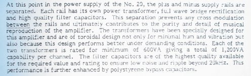
To show you that this too is old news i've added a picture of some lines from the ML20.5 brochure.
But dont let me keep you all from talking nuts and bolts again.
I have been looking at the Eagle files to check if i have all the parts with right leg spacings.
And am very pleased with the flexibility of these boards, so i am very satisfied to have been forced to enter this groovy groupy thingie.
Great job, Al !
Anyway, this led me to wonder whether there will a new BOM for this design ?
I figured a list of alternatives for the different components would be nice, and possible additives.
For starters i am not sticking to the exact resistor values/wattages and picking different type foil capacitors.
Before the weekend Mr Rollins posted a very good one on the Pass Monster thread about using MKP's bypassed by a polystyrene.
I am using polystyrene's for the frequency compensation alltogether.
Bypassing with polystyrene is something i would recommend for the Krell too.
It is something i have been doing for a long time, both in amplifier circuits as in PS's.
To show you that this too is old news i've added a picture of some lines from the ML20.5 brochure.
But dont let me keep you all from talking nuts and bolts again.
Attachments
Mark A. Gulbrandsen said:
I will check the Pabst site for measurement specs
Mark
http://www.papst.de/ (not pabst)
Jacco,
I certainly agree on the polys and bypassing. I do that too but mainly in preamps which is where it is the more critical. In this thread we are really trying just to keep the board all "stock" KSA-50. Part of the re-design was to add flexibility and to eliminate the current limiting feature that was on the 1st board. If you do variations please by all means post it here though. The board is really just a basis for all to begin with.
Over here of course it is Pabst but nothing to do with fans! This is the stuff one might drink alot of should smoke eminate from a feshly built KSA-50. Brewed in Mikwaukee, WI of course... The beer capitol if the World But it was never what I considered a good beer.
Mark
Attachments

Over 163K times viewed is more impressive.
MKP was suggested for the CRC boards, i wanted to point to the fact that there are many more improvements possible.
The boards are just fine, with plenty of room for geeks like me to place bulky capacitors, everyone to his own.
Say no more, you think i should order some Pabst upfront.
MKP was suggested for the CRC boards, i wanted to point to the fact that there are many more improvements possible.
The boards are just fine, with plenty of room for geeks like me to place bulky capacitors, everyone to his own.
Say no more, you think i should order some Pabst upfront.
AndrewT said:Hi Greg,
have another look at ESP's grounding. The diagram shows four separated grounds spread between the two central capacitors (speaker returns and signal grounds). This is clearly poor grounding practice.
I think you are referring to something else namely combining the dirty, power and signal grounds. Many views are held on this or using the resistor separation philosophy. I prefer the resistor separation but I did give Still4given the alternatives to let him choose/experiment for himself.
Could you clarify which camp you are in;- ESP's diagram is either right or wrong? grounds should minimise voltage differences across the reference points or grounds can be located at any varying voltage and to h..l with the deleterious effects on sound quality.
Yes you are right. I always use a common bolt for my connections just like still4given did. Personally I would never do it exactly like Rod's schematic but my gut feeling is it won't make much difference. It the kind of thing I will never try because it definitely wouldn't be better. If you think about it logically, if you are going to worry about 5 or 10 mm of copper (which is probably 2 or 3 mm thick) between these connections then you should also worry about matching the resistance of each wire leading from the star point. You have to draw the line somewhere.
Yep, when do you guys have in mind to order some boards? Not that I am in a hurry, just to knowYou have to draw the line somewhere.
Steen
OK another update.
I went ahead and unsoldered the boards from the drivers and checked them by themselves. I have 44VDC rails from my PSU but my voltages pretty much agreed with the wiki on page 4.
I tried adjusting the bias pot by measuring the voltage drop across the driver resistors. One board seemed to work and the other didn't. I then soldered them back up to the outputs.
I am now using a 150 watt light bulb in series ahead of the power transformer. I hooked up one channel at a time. The first channel powered up fine but the bias pot would not adjust anything. I rechecked the voltages from the wiki and everything checked out. I am getting about -857mV from the speaker output to ground.
I then hooked up the second board to the outputs and upon switching it on the 150 watt light bulb burned very brightly. I took a reading of the PSU and it was down to 17VDC. When I unsoldered the positive output lead on the board the PSU voltage went back up. So I started removing the PNP output transistors one at a time and checking by touching the output lead to the solder pad. Well two of the PNP outputs were bad so I replaced all three. Now everything checks out but I have -.5V from the speaker output to ground and I can't adjust the bias on this channel either.
So that's where I am at. If any of you fine folks are in the mood to offer some advice, I'm all ears.
Thanks, Terry
PS. The Ovation is on a stand. My wife thinks it dresses up the living room.
- Home
- Amplifiers
- Solid State
- Krell KSA 50 PCB