Yes, that's Kapton tape. Miracle of modern materials. Can take 400C I think and the silicone adhesive never leaves residue. It's pretty thermally conductive as well.
I still use a thin layer of heatsink paste on topside (underside of transistor), I dont know if you use it..
Last edited:
")
Thank you for doing such a nice layout and for the design credit. I appreciate it.
This link provides a circuit description of the original HPA design: Dual Class-A Line and Headphone Output Board Documents - Pro Audio Design Forum
Best;
Wayne
Thank you Mr. Wayne for your comments and your design and sharing the design and sch link..
regards
Prasi
X, thats a very nice build and the amp measures very good too!.
Thanks for sharing.
Regarding 30-35 BC designs, I agree that this design would be easier to trouble shoot too
I am listening to it now and am quite impressed with the sound - considering how deadnuts simple it is. There is a caveat with the THAT1646 HPA though: it's unity gain so an ultra low distortion current buffer. If you need gain, a gain stage up front is needed. For high sensitivity phones and IEMs 0dB gain works fine. Especially if you have high swinging DAC.
Wayne Kirkland has a lot of very practical solutions on the pro audio forum he linked.
This is old hat to some, but he pointed this out to me recenty: bootstrapped opamps that with 2 transistors on the rails can swing 70v p-p on +/-45v rails.

Pretty cool eh?
Last edited:

I'm surprised no one finds this FFT as interesting as I do. There is essentially no measurable distortion.
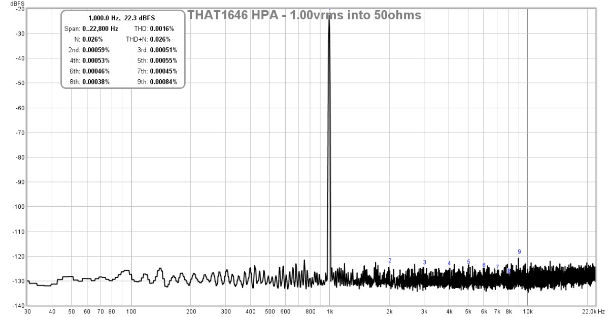
Also, look at the noise floor at 60Hz. The PSRR is phenomenal - I don't think I have seen something g like this from a basic linear trafo and 7815/7915 voltage regulators. There is no bump at 60/120/180Hz per usual suspects.
Also, look at the noise floor at 60Hz. The PSRR is phenomenal - I don't think I have seen something g like this from a basic linear trafo and 7815/7915 voltage regulators. There is no bump at 60/120/180Hz per usual suspects.
Last edited:
I was impressed! So impressed that I am building this as the output stage to a sophisticated EQ/ Audiophile preamp that I am crafting. I am hoping to realize similar numbers to what you are seeing.
The circuit designer, Wayne Kirkwood, says most of his customers are sound engineers who make mixing consoles and this is what they use this for - a preamp/line driver for EQ console.
Are you going to use Prasi's layout? 10 boards is $2 plus shipping from EasyEDA so a no-brainer...

The circuit designer, Wayne Kirkwood, says most of his customers are sound engineers who make mixing consoles and this is what they use this for - a preamp/line driver for EQ console.
Are you going to use Prasi's layout? 10 boards is $2 plus shipping from EasyEDA so a no-brainer...
Wow, the finished board price is certainly good but in my case the circuit will be on a larger PCB that also holds the EQ their controls.
I would post details of the finished EQ & preamp on this forum if I thought there was enough interest.
The circuit designer, Wayne Kirkwood, says most of his customers are sound engineers who make mixing consoles and this is what they use this for - a preamp/line driver for EQ console. ...
Here you go ...

Nice work Carl!
I noticed you have 3 separate heatsinks, the Kirkwood design calls for 3 of the outputs (2 x BD139 and 1x BD140) on the same heatsink for Vbe tempco. What opamps are you using for EQ stages?
Yea, I would have preferred to put all 3 BD devices on a common heatsink, however the heatsink that Wayne used isn't stocked by any of my vendors. As a compromise I put 2 devices on both sides of a common heatsink. That way vbe tracks one of the output device but not both. I would be interested if you have a good source for 3 place TO-220 heatsinks. By the way, what's the best way to set vbe? I am not convinced that I have set it optimally.
I used OPA2604s for op amps. They sound very good in this topology. The filters are bandpass at 40, 160 and 640 hertz. The Hi shelf is adjustable from 600Hz to 18kHz. The circuit is very quiet. I am struggling to find the noise floor using my aging Audio Precision Portable One.
I have been very happily using this when digitizing my old vinyl. It hits all of the bands that usually need touching up.
Last edited:
That's good that you have the Vbe multiplier tracking at least one of the BJT's. I normally drill and tap a larger heatsink like this one:
W6 Aluminum Heatsink Cooling Fin 150mmx60mmx25mm for Power Amplifier | eBay
W6 Aluminum Heatsink Cooling Fin 150mmx60mmx25mm for Power Amplifier | eBay
Yea, I would have preferred to put all 3 BD devices on a common heatsink, however the heatsink that Wayne used isn't stocked by any of my vendors. As a compromise I put 2 devices on both sides of a common heatsink. That way vbe tracks one of the output device but not both. I would be interested if you have a good source for 3 place TO-220 heatsinks. By the way, what's the best way to set vbe? I am not convinced that I have set it optimally.
The best way to set the Vbe is to read the output current indirectly via the emitter resistors. For headphone outputs I run it pretty hot around 85-95 mA. If you're using it for a line output the Iq can be considerably lower. I think Roger Foote used 25 mA in his transformer line driver outputs for the FCS Mastering compressors which are based on my circuit.
I know there's talk about using heatsink insulators: The Fairchild/ON BD139/BD140 have a plastic over mold and do not need them.
If the Vbe multiplier is reading one of the outputs it should track OK.
I should probably restate that the DRV134 can also be used but a 1/2 voltage divider needs to be between the Vbe ref and pin 4. The DRV has a gain of 4X through the Din pin when the part is used this way; the THAT1646's differential gain is 2X.
Last edited:
The best way to set the Vbe is to read the output current indirectly via the emitter resistors. For headphone outputs I run it pretty hot around 85-95 mA. If you're using it for a line output the Iq can be considerably lower. I think Roger Foote used 25 mA in his transformer line driver outputs for the FCS Mastering compressors which are based on my circuit ...
Wayne you are both a gentlemen and an excellent engineer!
I appreciate your detailed response. Thank you.
- Status
- This old topic is closed. If you want to reopen this topic, contact a moderator using the "Report Post" button.
- Home
- Amplifiers
- Headphone Systems
- ESP HPA