Yes, Carl, that EQ board is beautiful. Are you offering it as a GB?
Sure, it there is enough interest. Should I start a thread?
Sure, it there is enough interest. Should I start a thread?
yes, you should, to atleast gather interest, for such a lovely design by Mr. Wayne and yourself.
regards
Prasi
yes, you should, to atleast gather interest, for such a lovely design by Mr. Wayne and yourself.
regards
Prasi
Okay, I will put that on my weekend 'to-do' list. More coming ...
Sure, it there is enough interest. Should I start a thread?
Go for it Carl!
I adapted the original driver PCB to make a 10W Class-A amp. I powered it with two 18V laptop supplies.
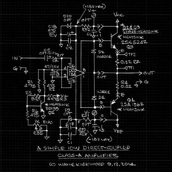
Schematic of a Simple 10W Direct-Coupled Class-A Power Amplifier Using a DRV134, 2SA1962 and 2SC5242.
On this schematic you can see the Vbe Multiplier's divider to scale the bias voltage for the DRV134's 4X differential gain.
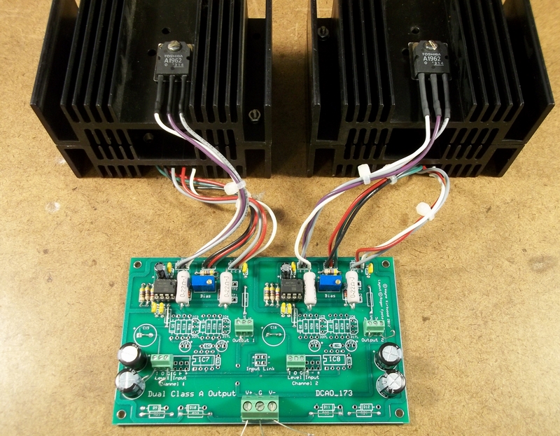
Here's a pic of it with output devices mounted on Augat "Ghostbusters Backpack" heatsinks.
A Simple 10W Direct-Coupled Class-A Power Amplifier - Pro Audio Design Forum
That's very nice Wayne. I assume the THD numbers are extremely low? This is 0dB gain voltage follower right? So this can be built on top of the current DRV134 DCA II PCB?
Perfect for the Aksa Lender preamp which can swing 40Vpp (I have tested it to 51Vpp). Only 25Vpp is needed for 10W into 8ohms though, so should have plenty of headroom.
Can those Toshibas be replaced with TTC5200 and TTA1943?
Although I just checked Mouser and ON/Fairchild has the 2SC5242OTU and 2SA1962RTU at very reaasonable $2.20 for qnty 10. Nice output BJT with 230V and 17amps capability.
Last edited:
I can't find DRV134 on Mouser but 1646 is fine...
Here is an URL to the DRV134 part on Mouser ... DRV134PA Texas Instruments | Mouser
As Wayne has already noted ...
If builders use the THAT 1646 part in place of the DRV134 as shown in the amplifier project, they need to not include the voltage divider that is required by the DRV134 and not required by the THAT 1646 part.
And just how is this superior to the O.P.'s "simple HPA by ESP"??
I have built both and the Wayne Kirkwood THAT1646 HPA s much lower distortion, probably the lowest distortion HPA I have measured.
Recall the FFT for 50hms 1Vrms (2.83vpp):
Last edited:
Ha, ha ..
I like it! Is there a reason why you used a DRV134 rather than the THAT 1646 part? Is the performance similar?
The 1646 has a little lower distortion. The DRV134 has a cleaner clipping characteristic when using the off-the-wall common mode drive of this circuit.
In conventional line driver applications, which do not use common mode drive, the 1646 is always my first choice.
The DRV134 and THAT1646 are both superior to the SSM2142 in this application. The SSM2142 doesn't have as good of internal resistors and has higher THD.
Wow!! That IS impressive!! I wonder if you could post the measurement made with the same test on the ESP amplifier.I have built both and the Wayne Kirkwood THAT1646 HPA s much lower distortion, probably the lowest distortion HPA I have measured.
Regarding the ESP headphone amplifier:
What is the purpose of the capacitors across the diodes?
How to calculate the transistor bias currents?
I had only 1K resistors instead of 6.8K for collectors of the transistors. It was too low value and one of the 2N3906 burned at higher rail voltage (around -13V). I used these generic transistors for testing the circuit.
How does the emitter resistors affect the current flow through the transistors? I used 1 ohm.
If I was able to calculate how much current is flowing, I could be more careful before upping the rail voltage.
Last edited:
You will need to repost the schematic and refer to actual component numbers.
You mean this schematic
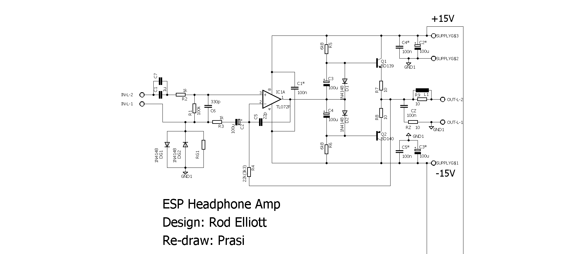
Calculate DC current through R5 then D1, D2 then R6. Assume zero current into base as first approximation. Diodes drop 1.3v so 30v-1.3v is total potential across two 6k8.
So I=V/R or 28.7v/13.8k or 2.1mA. If you used 1k it’s about 7x more or 14mA.
The actual value will be less since some leaks out to drive bases of transistor.
You mean this schematic
Calculate DC current through R5 then D1, D2 then R6. Assume zero current into base as first approximation. Diodes drop 1.3v so 30v-1.3v is total potential across two 6k8.
So I=V/R or 28.7v/13.8k or 2.1mA. If you used 1k it’s about 7x more or 14mA.
The actual value will be less since some leaks out to drive bases of transistor.
Last edited:
You will need to repost the schematic and refer to actual component numbers.
You mean this schematic
Calculate DC current through R5 then D1, D2 then R6. Assume zero current into base as first approximation. Diodes drop 1.3v so 30v-1.3v is total potential across two 6k8.
So I=V/R or 28.7v/13.8k or 2.1mA. If you used 1k it’s about 7x more or 14mA.
The actual value will be less since some leaks out to drive bases of transistor.
Thank you!
and do you divide that 14 mA in half to get what is flowing through each transistor Q1 and Q2, If so, 7 mA bias current through those is very low value.
Are the R7 and R8 resistors only functioning as current limiters for the whole circuit? Does their value affect how much current transistor will need to handle? I used 2N3904/2N3906 which can handle 200 mA continuous collector current and 625 mW of power consumption. 7 mA x 15 V = 105 mW idle power draw.
Is this Class AB circuit?
I tested the circuit using RMAA loopback test and it didn't work, it had high distortion.
I left out these components for simplicity:
C1 C7
R2 R1 C6 C2 DG2 DG1 RG1 CZ R9 L1 C4 C2 C5 C3
Last edited:
You left out most of the components and you say it doesn’t perform well? I wonder why - they are there for a reason as this is already a very simple circuit. You need C3,C4, C5 for sure. The currents through the 6k8 are to provide a DC bias to drive the outputs. The amount of current through the base is multiplied by the Hfe of the BD139/140. Or whatever you are using. This is Class AB but can be pushed to Class A by using smaller value R7 R8. You need bigger heatsinks though as it gets hot. I have run it Class A circa 100mA bias Andor did not sound better.
You left out most of the components and you say it doesn’t perform well? I wonder why - they are there for a reason as this is already a very simple circuit. You need C3,C4, C5 for sure. The currents through the 6k8 are to provide a DC bias to drive the outputs. The amount of current through the base is multiplied by the Hfe of the BD139/140. Or whatever you are using. This is Class AB but can be pushed to Class A by using smaller value R7 R8. You need bigger heatsinks though as it gets hot. I have run it Class A circa 100mA bias Andor did not sound better.
You are right. It didn't work as supposed to, because of the components were not used.
I was hearing FM radio through it, which is at 103,9 MHz, when source was connected. How is that possible, I don't know.
It needs to have those bandwidth limiting components there.
Even though the circuit seemed very simple, I ditched it, because It seemed to be so sensitive to interference at least on a perfboard.
Last edited:
It's not that many parts, why don't you try building it as the designer intended before saying it is too prone to interference? Heck, this is one of the simplest push-pull class AB high-quality headphone amps out there. Send me a PM if you want a PCB, no charge - just pay shipping.
- Status
- This old topic is closed. If you want to reopen this topic, contact a moderator using the "Report Post" button.
- Home
- Amplifiers
- Headphone Systems
- ESP HPA