Hey.
At the moment, I am an electronic engineer student, and I just finished my 3rd semester. So, there are still a lot of things that I don’t really understand, hence this post.
I want to design my own power amplifier. It is a pretty good exercise and there is something special about have a setup that I have designed.
So, the amp. The transistors I am using is chosen only be course I have access to them at the university. If this works in the real world, then I will redesign the amp and source some better transistors.
I really like the idea about a symmetrical amp, intuitively it seems right to me that the amp has the same capabilities for rising and falling edges. About the cascodes, I have just learnt about them, and well… it also seems right to me, to use a topology that reduces distortion. The output stage is simply stolen from Hawksford
So… I am hoping that someone will tell me if there is something really stupid in the design. Or give some pointers towards improvements. Before I build a prototype.
Cascode bias diode D1 makes me uncomfortable.
If there exists any ripple, noise, or output-current-related voltage modulation on the positive supply rail, diode D1 puts that noise on the base of the cascode transistors. I would much, MUCH prefer to reference the cascode base nodes to either (a) signal ground; or (b) tail node of differential input pair.
If there exists any ripple, noise, or output-current-related voltage modulation on the positive supply rail, diode D1 puts that noise on the base of the cascode transistors. I would much, MUCH prefer to reference the cascode base nodes to either (a) signal ground; or (b) tail node of differential input pair.

Member
Joined 2009
Paid Member
Hey.
At the moment, I am an electronic engineer student, and I just finished my 3rd semester. So, there are still a lot of things that I don’t really understand, hence this post.
I want to design my own power amplifier. It is a pretty good exercise and there is something special about have a setup that I have designed.
So, the amp. The transistors I am using is chosen only be course I have access to them at the university. If this works in the real world, then I will redesign the amp and source some better transistors.
I really like the idea about a symmetrical amp, intuitively it seems right to me that the amp has the same capabilities for rising and falling edges. About the cascodes, I have just learnt about them, and well… it also seems right to me, to use a topology that reduces distortion. The output stage is simply stolen from Hawksford
So… I am hoping that someone will tell me if there is something really stupid in the design. Or give some pointers towards improvements. Before I build a prototype.
View attachment 626134
The one piece of advice I have never listened to, or enjoyed receiving, was to start simple. In all my hobbies and endeavours the thing that interested me was often the more complicated and difficult route. And in all cases I had read about the exploits of others who were already doing it and they made it look so simple that surely I could start straight away in the deep end and avoid the boring journey to get there. I eventually failed to achieve the results I expected, didn't enjoy it very much, got frustrated and moved on. Now, only in my later years have I been able to design and build some nice amplifiers whilst also enjoying the journey. But I'm wise enough not to give advice that will fall on deaf ears

need the same fix for D2
mlloyd1
This is just embarrassing... and thanks
The one piece of advice I have never listened to, or enjoyed receiving, was to start simple. In all my hobbies and endeavours the thing that interested me was often the more complicated and difficult route. And in all cases I had read about the exploits of others who were already doing it and they made it look so simple that surely I could start straight away in the deep end and avoid the boring journey to get there. I eventually failed to achieve the results I expected, didn't enjoy it very much, got frustrated and moved on. Now, only in my later years have I been able to design and build some nice amplifiers whilst also enjoying the journey. But I'm wise enough not to give advice that will fall on deaf ears
Thank you for the advice, but the thing that drives me is the difficulty. If it is to easy i am too bored, and then I leave the project. However I have to admit that this project is more complicated then i thought at first. So I am in the thought process of deciding which way to go.
As a student, you will learn much better what is involved in a audio amp with a simple design based on a op amp based amplifier. This is basically an output stage ( a current booster ) with an op amp as a front end with massive feedbacks.That is the architecture of most audio amplifier made here where the op amp part is re invented made of discrete component.
IMO it is a waste of time for a student to reinvent this part in a project where the objective is a power amplifier with low distortion.
In case you want to go the way, all discrete including the front end part, go simple with P3A from Ron Elliot ESP.
IMO it is a waste of time for a student to reinvent this part in a project where the objective is a power amplifier with low distortion.
In case you want to go the way, all discrete including the front end part, go simple with P3A from Ron Elliot ESP.
Last edited:
Ummmm.... doesn't work other than in simulation, this is the already famous ill defined VAS current. Do yourself a favour before spending money on an implementation and calculate the Q14/Q15 collector current.
Well that is certainly a good point
So I am back to the drawing board, either cutting away the symmetrical par of the amp, or designing another VAS. And thank you, this was exactly the reason i made this thread
Well that is certainly a good point
And thank you, this was exactly the reason i made this thread
Wally is right. It is on the Randy Sloane's book, but it worked intermittent and it corrected on Bob Cordell's book.
As a student, you will learn much better what is involved in a audio amp with a simple design based on a op amp based amplifier. This is basically an output stage ( a current booster ) with an op amp as a front end with massive feedbacks.That is the architecture of most audio amplifier made here where the op amp part is re invented made of discrete component.
IMO it is a waste of time for a student to reinvent this part in a project where the objective is a power amplifier with low distortion.
In case you want to go the way, all discrete including the front end part, go simple with P3A from Ron Elliot ESP.
I disagree, a few weeks ago i designed and build a mostly discreet buck converter. With a discreet ramp oscillator, diff amp and driving circuit. I used opamps for the PID regulator. (so... this is not exactly my first amp, just my first amp for audio....) however, i could have used opamps for the osc, diff amp, and a big part of the driver. But then i wouldnt have learned nearly as much, my efficiency were +93%. (5v 1A output, asynchronous, and could have been higher with a more suited diode and mosfet)
I see this project the same way. In my view there is much more to gain, knowledge wise, by going discrete. However, right now i am trying to decide which way to go from here, regarding the complexity.
Going right away into details, which is the wrong way to go in early design.....:
The Zobel circuit is on the wrong side of the inductor.
So, are you saying that it would make more sense to use opamps were i can. And then remove them one by one as i design new discrete blocks? (as i really want a discrete design in the end) (or just saying that i should design and amp using op amps, and then the second amp could be more discrete)
Last edited:
This was my advice as a teacher.
For a project where the objective is an op amp design I would recommend designing one using discrete components.
In a project where the objective is a low distortion power amplifier re inventing the op amp is not the first way to go.
BTW What is your objective in terms of: Output power, distortion, thermal stability, efficiency, stability in term of phase and gain margin?
Anyway, that is your amp.
Last edited:
Yes, firstly design with one op amp and an output stage.
You can get right away distortion lower than 0.01% at 20Khz in spice.
This will hopefully end with a good low distortion well biased output stage and mastering negative feedback to go at the best performances.
Unfortunately, spice is no direct help about thermal stability.
Then, mastering this first step, you can go at replacing the op amp for a all discrete version where you'll have to tackle higher performance op amp design in the very high Gainbandwith and slew rate with very low distortion and noise.
The same issues as the original project, you would say, but...without the need of high output power and driving weird loads, speakers are far from 8 ohm resistors.
This was my advice as a teacher.
For a project where the objective is an op amp design I would recommend designing one using discrete components.
In a project where the objective where the objective is a low distortion power amplifier re inventing the op amp is not the first way to go.
BTW What is your objective in terms of: Output power, distortion, thermal stability, efficiency, stability in term of phase and gain margin?
Anyway, that is your amp.
That makes sense. And when i think about it, it was the same thing my professor said when i worked on the buck converter, so I will proberly go that way.
the only specifications i have at the moment are.
50W 8ohm, 200W 2ohm (I know the current output stage cant really do this)
THD below 0.01% at 20kHz, 50W, I dont know anything about other forms of distortion, but I am waiting on self's book on power amps, and cordell's as well. Also... I dont know if the goal is reasonable, but time will show.
I dont have an exact goal for efficiency, but since i will need 6 channels, i want it to be pretty good, and that is the reason for using the hawksford EC. I am hoping that it will help me to reduce bias currents while keeping a reasonable performance. (this might be quite a misunderstanding... but time will show)
In terms of thermal stabillity, if we are talking about linearity across a temperatur range, then i havent really thought about it untill now. if we are talking risk of thermal runaway, then it is something i think about, but i dont know how to specify it.
about phase and gain margin. I dont really know what is reasonable for the gain margin. But i would like my phase margin to be between 40-60 degrees. (I had actually already forgotten the importance of this... even though it is less then 3 months since i learned about it...
)and thanks for the questions and advice, was exactly what i needed.
50W 8 ohm is a good start, mostly typicall.
200W 2 ohm is involved, look closely at SOA and Beta drooping.
Efficiency:
Class A: Terrible efficiency, easy very low distortion.
Class B: Efficiency depends of quiescent current ( aka bias ). Choices are 2 EF output stage versus CFP output stage. Low qiescent current, optimal ??, hight qiescent current.
Thermal stability:
The issue has to do from the BJT's Vbe tempco. it's decrease with temperature makes it difficult to get a stable bias and is prone to induce thermal runaway. See Rod Elliot ESP discussions about this and CFP versus 2 EF. Getting a stable qiescent current over BJT temperature variations with output power is a challenge in Class B amplifiers.
Phase and gain margin are of a paramount importance. This will account for the stability of the looped system( stability, here means no oscillation ).
Unfortunately there are other causes of oscillations, but you will have enough of those to fight, you do not want to oversee looped linear system theory to go in a hopeless fight on this one.
I would aim at Phase margin 30° and gain margin 20dB.
Last edited:
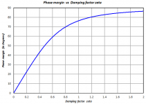
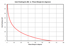
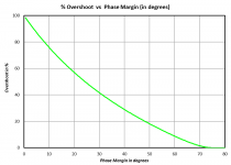
I've attached a pdf below, which discusses phase margin and other characteristics of second order linear systems (which are good approximations of power amplifiers & voltage regulators).I would aim at Phase margin 30° and gain margin 20dB.
My own personal preference to design circuits with phase margin of 65 degrees or more. This reduces overshoot to an acceptably low level, and keeps gain peaking modest.
_
Attachments
- Status
- This old topic is closed. If you want to reopen this topic, contact a moderator using the "Report Post" button.
- Home
- Amplifiers
- Solid State
- First amp ever, symmetrical and with EC