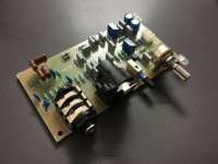
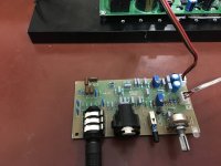
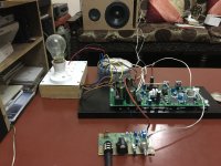
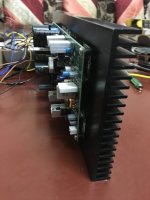
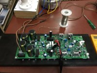
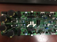
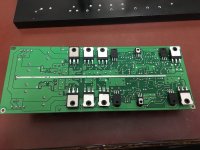
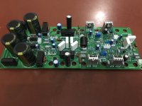
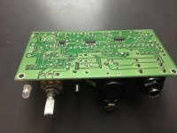
this is designed primarily for pro speakers. single or dual 12-15" drivers with a horn loaded compression driver . power output is scalable from 250-500W for LF and 50-100W for HF. active crossover is on a separate PCB with adjustable crossover frequency and a 80Hz switchable low cut filter and gain control and peak indicator.
some pics:
some pics:
Attachments
-
 IMG_0260.JPG280.7 KB · Views: 639
 -
 IMG_0283.JPG180.8 KB · Views: 163
 -
 IMG_0282.JPG223 KB · Views: 180
 -
 IMG_0280.JPG158.8 KB · Views: 193
 -
 IMG_0279.JPG230.8 KB · Views: 219
 -
 IMG_0278.JPG243.1 KB · Views: 591
 -
 IMG_0277.JPG210.3 KB · Views: 600
 -
 IMG_0269.JPG214.5 KB · Views: 611
 -
 IMG_0261.JPG220.4 KB · Views: 619
Here's the link to the complete album and video : Active speaker amp - Google Drive
your IN/OUT resistor values are very high.
R1, 2, 3 & 4 = 10k and R33 & 34 = 2k2
Why did you go so high?
Hi,
1. for R1....R4=10k, to provide a high impedance load for the source.
2. R33, R34=2k2, there are 2 reasons behind it, first: to prevent loading on the opamp U3, although 5532 can drive low impedance loads easily, but still, to lower the distortion and avoid oscillation and instability of opamp. second: to match the line level input of the power amp to put out specific power output.
Regards,
Aniket
What?Hi,
1. for R1....R4=10k, to provide a high impedance load for the source.
2. R33, R34=2k2, there are 2 reasons behind it, first: to prevent loading on the opamp U3, although 5532 can drive low impedance loads easily, but still, to lower the distortion and avoid oscillation and instability of opamp. second: to match the line level input of the power amp to put out specific power output.
Regards,
Aniket
Your answers don't make sense.
You have three 10k resistors loading each half of your source.
To me that adds up to 30k per half phase.
Any decent balanced source should be able to drive 600ohms.
The 2k2 output resistors are not the load on the final opamp, except when you accidentally short the output. The normal load on the opamps is 2k2+{120k||Rload}
Your chosen values are nonsense.
Last edited:
What?
Your answers don't make sense.
You have three 10k resistors loading each half of your source.
To me that adds up to 30k per half phase.
Any decent balanced source should be able to drive 600ohms.
The 2k2 output resistors are not the load on the final opamp, except when you accidentally short the output. The normal load on the opamps is 2k2+{120k||Rload}
Your chosen values are nonsense.
Hi,
Firstly, I will be using both balanced and unbalanced inputs, a pro mixer or any other pro audio source will drive a 600ohms load easily. but, any unbalanced source like a DAC or PC or a CD player or any other source you can think of, its better to have a high impedance load for them, to reduce distortion.
now the 2k2 output resistors, you mentioned right final load impedance is 2k2+120k, but if we remove 2k2 and if output gets shorted, then what?
you overlooked the rather more important point in my earlier post, the above values were chosen to match the line level input of the power amp to put out specific power output. and i preferred not to change the gain of the amplifier. End of story.!!!
I appreciate your contribution and teachings to the forum and you are a good critique, but we should read and understand the complete post before concluding something .
")
Cheers !
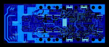
Nice project. Can we have the PCB layout ? Have You designed a protection circuit for it ?
Thanks.
yes i have designed a protection circuit with dc, short circuit, overload and thermal protect. will post soon.
the PCBs are dual sided with smd components also. hard to DIY.
Regards,
Aniket
your answers still don't make sense.
Output resistors are typically in the range 10r to 220r.
not 2k2.
Input resistors are typically in the range 100r to 2k
You have two 10k in series on each input.
That's 40k you have added for no benefit.
Output resistors are typically in the range 10r to 220r.
not 2k2.
Input resistors are typically in the range 100r to 2k
You have two 10k in series on each input.
That's 40k you have added for no benefit.
the opamp output current limiter takes over.then what?
your answers still don't make sense.
Output resistors are typically in the range 10r to 220r.
not 2k2.
Input resistors are typically in the range 100r to 2k
You have two 10k in series on each input.
That's 40k you have added for no benefit.
Yes they are, in the range 10-220R.
please tell the major advantages in reducing the values of IN/OUT resistors.
That is not what your .pdf is showing.Yes they are, in the range 10-220R.
your IN/OUT resistor values are very high.
R1, 2, 3 & 4 = 10k and R33 & 34 = 2k2
Maintaining the output voltage as the load impedance changes. This can be particularly cruel when you add in some RF attenuating capacitance.please tell the major advantages in reducing the values of IN/OUT resistors.
That is not what your .pdf is showing.
I was mentioning that yes, 10-220R is used generally.
Maintaining the output voltage as the load impedance changes. This can be particularly cruel when you add in some RF attenuating capacitance.
Thanks mate for the info. will it also reduce noise ?
Talking about Johnson noise:
A 1k0 resistor has the equivalent to ~4nV/rtHz of Johnson noise.
Add this to a power amplifier with an inherent 4nV/rtHz of self noise and you get ~5.7nV/rtHz of noise when referred to the input. This would be excellent.
Switch that resistor to 20k, now you are adding ~18nV/rtHz to the 4nV/rtHz of the amplifier to give ~18.3nV/rtHz of input referred noise. This is barely acceptable for a power amplifier.
Apply the same 1k & 20k comparisons to a pre-amp gain stage and you have a good stage becoming bad, just because you have placed 20k in the input leads.
- Status
- This old topic is closed. If you want to reopen this topic, contact a moderator using the "Report Post" button.
- Home
- Amplifiers
- Solid State
- Amp module for 2 way active speakers