Until a few years, the rule was : "avoid the ground loops". In fact it is only a recipe (obsolete ?) and is scientifically questionnable.
Recent approaches are much more analytical and consider why and how parasitics appear in the useful signal+ground path.
The 10 Ohm resistor of post #1 may a be useful remedy in some cases where hum appears. But to me, the presence of hum indicates that general ground scheme is less than ideal.
It there any proof that the 10 Ohm resisor always gives lower noise ? Only a few of renowned authors seem to use it.
HBR ?
Ground loop currents are simply the result of a loop circuit being intersected by a magnetic field. You cannot avoid them, only minimize them. It's physics.
Of course. But what matters if the purity of the signal, not the existence of ground loops.
In sub-optimal layouts. For those who ignore the existence of different approaches, see many of the posts by member herve00fr :The rule still applies
http://www.diyaudio.com/forums/search.php?searchid=15945154
For some measurements, see :
Attaching preamp in/out signal grounds at chassis vs. on PCB
and the following posts up to the current end of the thread.
Herve is still waiting comments and objections.
Herve was told that the two extremes that he tested for were unreasonable.....................
Herve is still waiting comments and objections.
That resulted in answers that could not easily be applied to real performance.
He refused to add any other more reasonable testing regimes.
I dont know what Herve's test set up was, but measuring the amplifier without a source attached it's easy to get good measurements. Measure with a preamp or other real world source attached and you will see the effects of ground loops and especially the cross channel ground loop.
The HBR is an industry accepted technique for solving the problem in unbalanced connections.
Signal purity has nothing to do with the issue. Your signal can be as pure as you like, but the presence of a GL will render it anything but.
The HBR is an industry accepted technique for solving the problem in unbalanced connections.
Signal purity has nothing to do with the issue. Your signal can be as pure as you like, but the presence of a GL will render it anything but.
Hi Forr, it's relatively easy to have low (no noticeable) hum, having one channel setup.
The problem may arise as soon as you have two or more channels, connected to the source with separate cables (separate ground for each channel). In this case, two input terminals' grounds appear connected to each other at the other end of the cable - that's where the ground loop may appear.
Lifted ground (through 10R or so resistors) is an efficient technique for that kind of situation, assuming overall grounding is arranged the right way otherwise.
Cheers,
Valery
A loop must have the shape of a loop. Two shielded cables for a stereo connection (with their shields connected both at the ouput of the source and at the input of the receiver) kept well parallel as already mentionned have not the shape of a loop.The problem may arise as soon as you have two or more channels, connected to the source with separate cables (separate ground for each channel). In this case, two input terminals' grounds appear connected to each other at the other end of the cable - that's where the ground loop may appear.
The voltages induced in each shield being equal, there is not current circulating in the cables. This configuration is used almost everywhere with stereo cables having RCA plugs, are there many complaints about hum ? Remember the time of tape recorders, there were even cables with 2 * 4 RCA plugs.
Why this technique is not universally used and not in favor among all the great audio amps names ?Lifted ground (through 10R or so resistors) is an efficient technique for that kind of situation, assuming overall grounding is arranged the right way otherwise.
Cheers
Thanks for the information. I hope the HBR has some consideration for Keith Armstong and for people mentionned here :The HBR is an industry accepted technique for solving the problem in unbalanced connections.
A simplified universal differential or single ended phono preamp
Maybe a misinterpretation from me about the word "purity". To me, the preservation of signal purity is the aim of high fidelity, so it is a concern at every stage of the whole sound reproduction process.Signal purity has nothing to do with the issue. Your signal can be as pure as you like, but the presence of a GL will render it anything but.
Most commercial amps do not connect the RCA shield to ground where they enter the chassis. That's why they are supplied with plastic insulating washers, or why the housings are plastic. See for example Kobicon. The shield connection is usually tied to the chassis through a low value cap (~1nF) at the point of entry which at RF makes the shield and the metal housing one conductor - very effective.
HBR = Hum Breaking Resistor not to be confused with a ground lifter which is something entirely different
HBR = Hum Breaking Resistor not to be confused with a ground lifter which is something entirely different
Last edited:
A loop must have the shape of a loop. Two shielded cables for a stereo connection (with their shields connected both at the ouput of the source and at the input of the receiver) kept well parallel as already mentionned have not the shape of a loop.
The voltages induced in each shield being equal, there is not current circulating in the cables. This configuration is used almost everywhere with stereo cables having RCA plugs, are there many complaints about hum ? Remember the time of tape recorders, there were even cables with 2 * 4 RCA plugs.
Why this technique is not universally used and not in favor among all the great audio amps names ?
Cheers
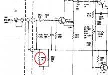
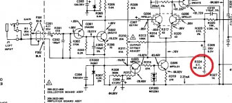
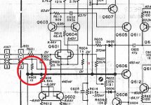
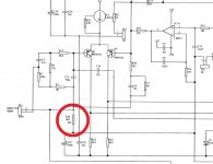
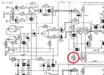
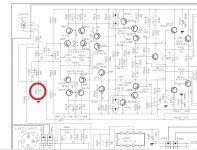
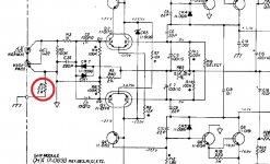
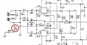
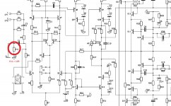
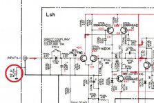
Attached are some input stage fragments from well-known manufacturers - all of them use this technique:
01 Marantz 250M
02 Marantz 510M
03 Marantz PM94
04 Perreaux 200i
05 Perreaux 6200B
06 Rotel RB1090
07 SAE 2401
08 SAE X-25A
09 Lab Gruppen FP2400
10 Hitachi HMA-6500
If you assume RCA shield is not connected to the chassis - you will see the ground wires inside the amplifier + two shields of the cable form a pretty evil loop (the longer the cable is - the longer the loop is). This is not the case in case of dual-mono setup with separate grounds - that's why some manufacturers use this configuration. Monoblocks - radical solution of the problem
")
Cheers,
Valery
Attachments
-
 01 Marantz-250M-pwr-amp.jpg82.6 KB · Views: 249
 -
 02 Marantz-510-M-pwr-amp.jpg142.1 KB · Views: 244
 -
 03 Marantz-pm94-pwr-amp.jpg162.2 KB · Views: 243
 -
 04 perreaux_200i_-pwr-amp.jpg60.2 KB · Views: 226
 -
 05 perreaux_6200b_pwr_amp.jpg135.9 KB · Views: 228
 -
 06 Rotel-RB1090-pwr-amp.jpg157.3 KB · Views: 111
 -
 07 sae_2401_pwr_amp.jpg153.3 KB · Views: 125
 -
 08 sae_x-25a_pwr_amp.jpg123.2 KB · Views: 100
 -
 09 lab-gruppen_fp2400_pwr_amp.jpg127.9 KB · Views: 103
 -
 10 hitachi_hma-6500_pwr_amp.jpg137.6 KB · Views: 112
"A loop must have the shape of a loop. Two shielded cables for a stereo connection (with their shields connected both at the ouput of the source and at the input of the receiver) kept well parallel as already mentionned have not the shape of a loop. "
No - this is not correct.
Any circuit is a loop. Any magnetic field impinging on any part of the circuit - be it between the shield and the central conductor or within the circuit inside either the transmitter or the receiving equipment will generate an EMF that will cause current to flow around the circuit.
The key issues is to keep the LOOP AREA as small as possible and this is the main reason for using interconnect cables that have the signal and return closely coupled in unbalanced connections. Shields have virtually no effect at audio frequencies (different story at RF) - its the fact that the loop area is minimized that reduces hum.
The key issues is to keep the LOOP AREA as small as possible and this is the main reason for using interconnect cables that have the signal and return closely coupled in unbalanced connections. Shields have virtually no effect at audio frequencies (different story at RF) - its the fact that the loop area is minimized that reduces hum.
I picture the ground loop like a loop aerial and so the larger the area the more interference it can pick up. But you are talking about the send and return loop?
Hi,
I spent a bit of time reading DiyAudio posts on the subject of ground connections especially those of members Speedskater and Marce because they much refer to experts who have experience not limited to audio. Views are often radically different from those wich are the most popular in audio
Measurements apparatus have their sockets not isolated from the chassis.
- a pair of long wires very close to each other
- and for a pair of shorter wires but separated by a distance such as the loop area is equal to the first pair
?
What would give a stereo unbalanced cable made of two shielded cables as usual but with the shields in electrical contact all the way
?
I spent a bit of time reading DiyAudio posts on the subject of ground connections especially those of members Speedskater and Marce because they much refer to experts who have experience not limited to audio. Views are often radically different from those wich are the most popular in audio
So interferences enter the chassis (ref. Keith Armstrong).Most commercial amps do not connect the RCA shield to ground where they enter the chassis.
Measurements apparatus have their sockets not isolated from the chassis.
More effective is the shield connected to the chassis (many refs)The shield connection is usually tied to the chassis through a low value cap (~1nF) at the point of entry which at RF makes the shield and the metal housing one conductor - very effective.
For the same resistance and connections at both ends, will the current be the same forForr > A loop must have the shape of a loop. Two shielded cables for a stereo connection (with their shields connected both at the ouput of the source and at the input of the receiver) kept well parallel as already mentionned have not the shape of a loop.
No - this is not correct.
Any circuit is a loop. Any magnetic field impinging on any part of the circuit - be it between the shield and the central conductor or within the circuit inside either the transmitter or the receiving equipment will generate an EMF that will cause current to flow around the circuit.
The key issues is to keep the LOOP AREA as small as possible and this is the main reason for using interconnect cables that have the signal and return closely coupled in unbalanced connections. Shields have virtually no effect at audio frequencies (different story at RF) - its the fact that the loop area is minimized that reduces hum.
- a pair of long wires very close to each other
- and for a pair of shorter wires but separated by a distance such as the loop area is equal to the first pair
?
What would give a stereo unbalanced cable made of two shielded cables as usual but with the shields in electrical contact all the way
?
This would be very good, do you know of such a cable?What would give a stereo unbalanced cable made of two shielded cables as usual but with the shields in electrical contact all the way
?
Attached are some input stage fragments from
well-known manufacturers - all of them use this technique[...]
If you assume RCA shield is not connected to the chassis - you will see the ground wires inside the amplifier + two shields of the cable form a pretty evil loop (the longer the cable is - the longer the loop is). This is not the case in case of dual-mono setup with separate grounds - that's why some manufacturers use this configuration. Monoblocks - radical solution of the problem
I do not deny that the Hum Breaking Resistor is used by quite many manufacturers. Are they the majority ?
Many stereo amps with only one power supply do not have it and they are absolutely hum free (my Self Blameless for example).
I hope dual monoblocks builders have better reasons than hum suppression to build them
I am interested by all schemes and by comparisons between them.At the same time - this is not the only solution possible - there are other good ways to arrange grounding the right way.
Hi,
I spent a bit of time reading DiyAudio posts on the subject of ground connections especially those of members Speedskater and Marce because they much refer to experts who have experience not limited to audio. Views are often radically different from those wich are the most popular in audio
So interferences enter the chassis (ref. Keith Armstrong).
Measurements apparatus have their sockets not isolated from the chassis.
More effective is the shield connected to the chassis (many refs)
For the same resistance and connections at both ends, will the current be the same for
- a pair of long wires very close to each other
- and for a pair of shorter wires but separated by a distance such as the loop area is equal to the first pair
?
What would give a stereo unbalanced cable made of two shielded cables as usual but with the shields in electrical contact all the way
?
There are many fine amplifiers out there that use the techniques described that do not have noise problems (hum or RF). They have minimized loop areas, used sound RF filtering techniques, and used HBR (see Valery's list).
I have two signal generators on my bench (ITT and BK) that are in plastic boxes. They have no problems.
I do not understand your last question
You need to separate ground loop noise (hum) and RF noise in the discussion. It may help clarify the subject.
- Status
- This old topic is closed. If you want to reopen this topic, contact a moderator using the "Report Post" button.
- Home
- Amplifiers
- Solid State
- Input Resistor