You just proved you don't have any strong arguments, so yeah you shouldn't bother.Well that says it all. The guy who wrote the book on ESLs and you can't recall the name.
I don't see the need for a specific thread on this, thanks.
Jan
That guy might be first, but many books were written after him, using that info and even if they mentioned him, you wouldn't recall his name 18years later -which is when I designed my current ES amp and ES headphones (in 2000) (all to be redesigned and replaced soon) and I even bought one book I found locally about ESL design, but there was no mention about headphones -I had to do my own research from scratch. Back then, the internet resources about headphones were very limited.
Exactly, and slew rate can be replaced by power bandwidth for the reasons I have mentioned previously.It's really not worth ruminating about because the vast majority of home-use, discrete amplifier circuits can easily meet the slew rate spec. Many, especially older, op-amps do not and that is what Walt wrote about in 1979.
That said, there is still a huge problem driving ESLs directly (without transformers) with an amp, due to the excessive capacitive currents that exceed all current transistor and mosfet specs (for a 20Khz power bandwidth). You need to parallel and/or put in series a lot of mosfets to do that, which will skyrocket the cost and might limit lowering THD and due to the trend of making them for switching-only applications, there is still a huge reliability problem.
Last edited:
This week I was searching to find just the right part for an audio project, and I came upon this delightful graph (below) in a datasheet by Analog Devices. The graph reminds us that it takes some seriously large delta-V across the differential input, to make the IPS lean all the way over and steer 99.99% of the tail current into one side or the other -- i.e. slew rate limiting.
It also reminds us that delta-V across the differential input is, in fact, an error. Obvious, but also easy to forget.
_
It also reminds us that delta-V across the differential input is, in fact, an error. Obvious, but also easy to forget.
_
Attachments
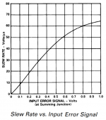
I suspect that is a specific graph for a particular IC. The voltage swing can be adjusted with different degen resistors, and the slew rate depends on the gm and compensation capacitor. An undegenerated bipolar input stage will hit max. slew rate at about +/-120mV.
So it depends on what you design. Or you can select a suitable IC.
So it depends on what you design. Or you can select a suitable IC.
Last edited:
Are you sure?It also reminds us that delta-V across the differential input is, in fact, an error. Obvious, but also easy to forget.
Yes, the difference voltage between the bases of a diff amp is called the "error signal". Ideally the bases are always at the same potential, and through feedback this is what any gain block is trying to achieve - both inputs at the same level.
The scale for the x-axis on the graph in post-263 must be wrong, or as John Ellis says, it is for a specific circuit with high degeneration resistors. Besides which, there is no correlation between the input stage slew rate and the error level except at the point of clipping the output of the diff-amp. So, the graph is meaninglyess without the context of the circuit.
Maybe you could post a link to the article?
It's a figure from the datasheet of one particular Analog Devices opamp, whose slew rate is listed as "50 V/usec minimum, 75 V/usec typical".
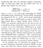
This specific opamp has a differential pair of P-channel JFETs at the input, which allowed Analog Devices to set GBW (= gm/Cc) and slew rate (=Itail/Cc) to the desired values, while using a small compensation capacitor Cc. In BiFET opamps, the compensation capacitor(s) occupy huge amounts of die area, so a small Cc is desirable. It lets you build a smaller die, so you get more gross die per wafer and (via defect density) you also get higher ratios of (sellable_die / gross_die). This particular AD opamp has a Cc which is 0.4x the Cc of the uA741 opamp.
James Solomon's oft-quoted paper "The Monolithic Op Amp: A Tutorial Study" talks about the slew rate advantages of JFET input opamps (attachment below) and Bob Cordell's power amp textbook covers JFET input stages rather well.
_
Attachments
Last edited:
It's a figure from the datasheet of one particular Analog Devices opamp, whose slew rate is listed as "50 V/usec minimum, 75 V/usec typical".
AD744 says
 to all of you.
Apparently, one of those opamps that sounds really nice ... if you skip the class B output stage via the compensation pin (5)
")
- Status
- This old topic is closed. If you want to reopen this topic, contact a moderator using the "Report Post" button.
- Home
- Amplifiers
- Solid State
- Slew Rate