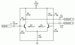
First question, only because I don't feel like looking up the datasheet, will those transistors support a Vce of 220?
Ok, you've got 120k of resistance per leg. From a 220 volt source, that's 1.83mA of bias current. That's reasonable. But the collectors of your Qs is at 37Volts. This means your +/- swing will be limited on the - side. You should try and bias the collectors at 1/2 VCC.
Secondly, since you've got 100k of collector resistance, your gain is going to be pretty high (gm*Rc ~ 7800) so your input signal level will be very sensitive.
Do you just need a phase splitter? You might want some emitter resistance. If you make Rc and Re about equal, you'll have something that does a gain of 1. Maybe split up your 100k into 2 50ks. You'll have to adjust your bias a bit.
svokke said:I want a solid state phase splitter in a tube amp. I can't use a tube, because my transformer can't supply more heater current.
This is my first solid state phase invertor, so please check if it will explode, do nothing useful or work.
i was thinking of a similar thing in my post http://www.diyaudio.com/forums/showthread.php?s=&postid=353069#post353069 , ..although this would be close to the input (maybe preceeded by a tube buffer)
the downside is that you would require a +/- 15V supply for the DRV134 line driver / phase splitter opamp
if tube heater current is your only limitation, why not just buy a small filament transformer to address that issue?
the one (really dumb and naive) question i have about this opamp (not being a SolidState DIY'r) is "what governs the output voltage of the line driver, the input or the supply voltage?"
regards
I tried simulatin the circuit using LTSpice, but I didn't succeed in that. I just couldn't get 2n6517 to work in the program. So I simulated it with the demo version of circuitmaker.
I used a current source made of a lm317 regulator. It simulates a lot better than a plain transistor in the tail position. I can't use it in the real world though because it needs more current going through it to work well. What kind of current source would you recommend?I would replace R3 with a current source.
In my simulations, gain is 31 (with a current source as tail) I think this is ok, the tube counterpart in fender/marshall/vox amps has an even larger gain.Secondly, since you've got 100k of collector resistance, your gain is going to be pretty high (gm*Rc ~ 7800) so your input signal level will be very sensitive
Vce max is 350V for this transistorFirst question, only because I don't feel like looking up the datasheet, will those transistors support a Vce of 220?
- Status
- This old topic is closed. If you want to reopen this topic, contact a moderator using the "Report Post" button.
