Hello friends of DIYAudio,
In last times I am making a lot of measurements, and someimes I like to dissect some projects, like this I show here: one Germanium amplifier, and a Germanium preamplifier. Both more or less "classics". The amplifier in one using AD161/AD162 output transistors, and the preamp is like one published in Discrete design: 2-transistor RIAA preamp (the Linsdale MM, with some minor alterations).
In next posts I will show the results (and I need to draw the schematics ) normally I build things WITHOUT schematics
In last times I am making a lot of measurements, and someimes I like to dissect some projects, like this I show here: one Germanium amplifier, and a Germanium preamplifier. Both more or less "classics". The amplifier in one using AD161/AD162 output transistors, and the preamp is like one published in Discrete design: 2-transistor RIAA preamp (the Linsdale MM, with some minor alterations).
In next posts I will show the results (and I need to draw the schematics
) normally I build things WITHOUT schematics 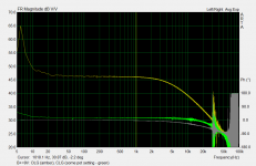
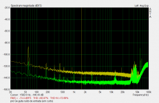
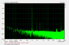
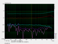
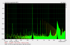
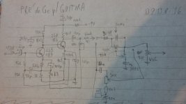
FF result for 500mV output with 5k load, and HD sweep for almost same level and same load, 20 to 30000Hz, showing individual harmonics (but 6H+ is summed)
I don't have this pre anymore; this are old measurements from last year (I've made this pre for a guitar player).
The schematic is at home, but tomorrow I post it.
EDIT: I used japanese Ge transistors instead of OC originals.
I don't have this pre anymore; this are old measurements from last year (I've made this pre for a guitar player).
The schematic is at home, but tomorrow I post it.
EDIT: I used japanese Ge transistors instead of OC originals.
Attachments
Now time for power amplifier...
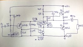
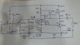
...for it I have draw the schema now!
Is a conventional amplifier for AD162/2 usage, but I used Ge even for input (a low noise 2SB486), and bias differ from originals. The missing values for input bias I don't remember now but is only to match the quiescent output voltage.
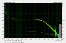
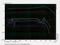
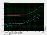
Some results for (please see the figure notes, at lower left): measured open loop vs actual use closed loop, FFT for open loop condition, HD sweep for open loop condition, FFT for low output bias (~<20mA) and high bias (approx. 200mA).
First time I have built this amplifier is in 1996, when I found some Telefunken AD161/162 from a old car radio, and tried a classic circuit model, with success (in mono). Since then, I have made some betterments (from simulations, 2008; from measurements, in 2009), stereo version (2012) and a cabinet for it. I have fused the original Telefunken's in 2011 . Is far from being my better or preferred amp, but is like a timeline for me, since I have it from my DIY beginings (1996)... In fact, is the second amplifier I've made in my first DIY year.
...for it I have draw the schema now!
Is a conventional amplifier for AD162/2 usage, but I used Ge even for input (a low noise 2SB486), and bias differ from originals. The missing values for input bias I don't remember now but is only to match the quiescent output voltage.
Some results for (please see the figure notes, at lower left): measured open loop vs actual use closed loop, FFT for open loop condition, HD sweep for open loop condition, FFT for low output bias (~<20mA) and high bias (approx. 200mA).
First time I have built this amplifier is in 1996, when I found some Telefunken AD161/162 from a old car radio, and tried a classic circuit model, with success (in mono). Since then, I have made some betterments (from simulations, 2008; from measurements, in 2009), stereo version (2012) and a cabinet for it. I have fused the original Telefunken's in 2011
. Is far from being my better or preferred amp, but is like a timeline for me, since I have it from my DIY beginings (1996)... In fact, is the second amplifier I've made in my first DIY year.Attachments
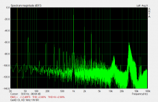
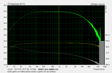
Result for 1W/8R/20Vcc/250mAiq for this amp.
Is a fair result for a such simple amplifier, with early transistors, all alloy type (low Ft).
I like the ground connection for the "second stage" ("VAS"), is less prone to suplly ripple, but... maybe the bootstrap have less PSRR than the stage gain, if stage is the "classic" Vcc based? In 2009 I simulated this and preferred the VAS in ground instead Vcc.
Attachments
I have a portable radio that uses GE transistors that belonged to my dad from the 1960's. I remember listening to it, & it still works & sounds nice as it did. Not HiFi, but a nice sound & has bass too None of that awful tinny sound many had !
All the best with your adventures
None of that awful tinny sound many had ! All the best with your adventures
What low noise transistor?!
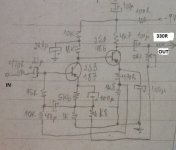
Here is the preamp schema.
Contrary to "common sense" when one don't have full knowledge about electronics like me, is that the lowest noise transistor need to be employed at input. Wrong. The second transistor/stage have higher gain in this design than the input, so I used the low noise 2SB486 in second stage, and more modest noise figure 2SB187 in input! Result: at least 10dB less noise than if one use the lowest .noise transistor in input and higher noise at second stage (output)...
This is measured in practice. What is going here in theory? Is about the stage gain I mentioned? Or stage impedance?
Attachments
In 2011, I add a knowed trick in this amp output: a output current feedback, to lowering damping factor. With moderate Zi (like 2R), allied with the "finite" distortion, sounds like some tube amplifiers, but with irrestrict bass. (note the 0R12 and two 4R7 resistors network from load to feedback negative input)
This Ge amplifier here really "don't have the right to sound good as it sounds in reallity", ie. is a good sounding one.
This Ge amplifier here really "don't have the right to sound good as it sounds in reallity", ie. is a good sounding one.
Attachments
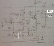
The corrected schema, sorry...Here is the preamp schema.
Contrary to "common sense" when one don't have full knowledge about electronics like me, is that the lowest noise transistor need to be employed at input. Wrong. The second transistor/stage have higher gain in this design than the input, so I used the low noise 2SB486 in second stage, and more modest noise figure 2SB187 in input! Result: at least 10dB less noise than if one use the lowest .noise transistor in input and higher noise at second stage (output)...
This is measured in practice. What is going here in theory? Is about the stage gain I mentioned? Or stage impedance?
Attachments
http://www.diyaudio.com/forums/solid-state/300107-new-amp-germanium-transitors-ad161-162-a.html
I liked the spirit of using an old amplifier. I made several amplifiers using old PCBs from commercial products.
Probably measurements for it differs from mine, due to silicon transistors usage.
I liked the spirit of using an old amplifier. I made several amplifiers using old PCBs from commercial products.
Probably measurements for it differs from mine, due to silicon transistors usage.
Thanks! (sorry about late response but now I have spare time)I have a portable radio that uses GE transistors that belonged to my dad from the 1960's. I remember listening to it, & it still works & sounds nice as it did. Not HiFi, but a nice sound & has bass too
All the best with your adventures
Very cool to know!
This remember when I repaired a old germanium-based 60's radio with a cabinet sized like tube radios. Sounded very good with the first audio stage cap open. But that are the reason why owner asks me to repair: low audio gain. I replaced the capacitor and sound become less good, but surprising for a old radio with trafo coupled stages.
Famous people here in forum love old germanium radios (Telefunken Bazzajo in John Curl case).
One thing that germanium definitely have is a smoother crossover distortion due to "semi-remote" cut-off, helping in some cases. If I measure a silicon amp with class B bias, the harmonics will spray flat until the audio board response limit, but in case of this little amp, the harmonics have decay and stopped less than 50kHz, like in high bias/low bias graph.
I have other Ge amp but is a subject for another thread in future.
Last edited:
This capacitor position seem to be strage at first glance, but it is a network "trick" (bootstrap) for making higher Z input. If you connect the capacitor like in your post, the input Z will be ~15k. In fact the stange connection is a positive feedback: in post #2, the open loop response has a huge peak at low frequencies, probably due a mismatch between capacitor values (is a side effect). In practice, my schema values makes a lot of motorboating, depending upon source Z input.
In fact, if low impedance is not a problem, I recommend to build one with your schematic modification. Will be far more stable.
Thanks for noticing this! So that I remembered this oscillation problem.
In fact, if low impedance is not a problem, I recommend to build one with your schematic modification. Will be far more stable.
Thanks for noticing this! So that I remembered this oscillation problem.
I have other Ge amp but is a subject for another thread in future.
I am interested
Generally wondering about Ge Transistors, I just purchased like 10 different types via ebay. Built my first amp from those and it sounds like it got a waterfall inside.This Ge amp I mentioned is like old "booster" car amplifiers with inductors, but using the Susan Parker's Zeus amp discipline for making the transformers. It uses 9V supplyI am interested
Have fun with Ge projects!
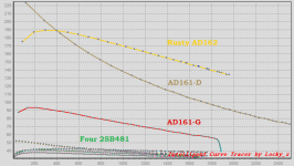
Some transistor measurements
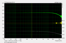
I have only 2 AD161, and my amplifier is a stereo one. So I use the 2. One of them have a too much downward beta, and have a suspicious high low current beta (like high leakage). Other have a fair beta variation but "stops" amplifying past 1.8A. Since the base network have low Z, even the high leakage AD works flawlessy here.
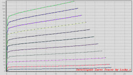
Four 2SB481 are measured. The two most linear are used in actual amplifier. They all have low beta, but at least a linear one. Since the "VAS" is a NPN and pull all current we want (limited by first stage), the PNP can be a low beta one and works OK.
A rusty spare AD162 is included for comparision.
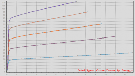
The second graph is from 2SB481, and last graph is from 2SB486 (the low noise input)
I have only 2 AD161, and my amplifier is a stereo one. So I use the 2. One of them have a too much downward beta, and have a suspicious high low current beta (like high leakage). Other have a fair beta variation but "stops" amplifying past 1.8A. Since the base network have low Z, even the high leakage AD works flawlessy here.
Four 2SB481 are measured. The two most linear are used in actual amplifier. They all have low beta, but at least a linear one. Since the "VAS" is a NPN and pull all current we want (limited by first stage), the PNP can be a low beta one and works OK.
A rusty spare AD162 is included for comparision.
The second graph is from 2SB481, and last graph is from 2SB486 (the low noise input)
Attachments
- Home
- Amplifiers
- Solid State
- A little study about two old germanium projects