Hello, i recently built a small preamp kit, and after bulding it, and firing it up, it seemed to have a tremendous amount of distortion. The distortion is plainly audible, and after checking the connections, i noticed that the ground isn't wired correctly.. Could this be the source of the problem?? Or is there something more? What would be the best way to track down this problem?? Tia
Dave
Dave
Well Dave, I or anyone else for that matter need to know more about the circuit. Just what preamp is this, a circuit diagram would help a lot. A disciption of what the distortion sounds like would help too.
You need some way to make a few measurements to find out what is going on with the circuit. With out that anything I or anyone else says would just be a wild guess.
Later BZ
You need some way to make a few measurements to find out what is going on with the circuit. With out that anything I or anyone else says would just be a wild guess.
Later BZ
distortion description
Here is the what the distortion sounds like- when you first power up the preamp, everything is quiet, and then if you start the music, it plays fairly cleanly for a few seconds. After that, the sound becomes very garbled and disgusting sounding. Hope this helps! Tia
Dave
Here is the what the distortion sounds like- when you first power up the preamp, everything is quiet, and then if you start the music, it plays fairly cleanly for a few seconds. After that, the sound becomes very garbled and disgusting sounding. Hope this helps! Tia
Dave
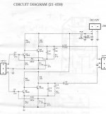
Check collector voltages wrt earth.
C of Q2 should be around 8V; C of Q1 should be around 4V.
Then measure the voltages across the emitter resistors and calculate the current flowing by Ohms Law.
Do this at no signal immediately on switch on, and follow the voltage carefully for the first ten minutes. If it changes after a short time, it's likely to be a cap. First one to look at would be C1, then C3, then C2. Often it's easier to just swap them out and see if it makes a difference. Remember, you are finding a fault quickly, not agonizing over methodology.
Cheers,
Hugh
replacing capacitors
Which capacitors should be replaced, the electrolytic ones, or the ceramic disc ones? A friend of mine also mentioned to me that these are very heat sensitive, and since i have a high wattage soldering iron they could have just been melted What is a good wattage iron to work with for soldering these? Also, if this preamp does turn out nice, which capacitors could be upgraded to nicer ones later on?? tia
Dave
Which capacitors should be replaced, the electrolytic ones, or the ceramic disc ones? A friend of mine also mentioned to me that these are very heat sensitive, and since i have a high wattage soldering iron they could have just been melted
What is a good wattage iron to work with for soldering these? Also, if this preamp does turn out nice, which capacitors could be upgraded to nicer ones later on?? tiaDave
voltages
Hdtvman,
Are you testing the actual voltage at the transistors themselves, or the capacitors after them? If so, which capacitors do you mean? How exactly would you do this- put the positive lead and negative lead from the multimeter on each end of the capacitor? Also, there are different voltage settings on the multimeter. Since the power supply for this project is 12v dc, would i use one of the dc settings? There are a few choices: 60v, 12v, 3v, 0.6v.. thanks!

signal
The input of the preamp is being fed by a Rotel Rcd-02 cd player, which is a 2 volt signal. The funny thing about the schematic for this is that there is no volume control in this, so i'm beginning to wonder if i'm using this circuit for the wrong purpose. The manual itself calls it a "stereo preamplifier" , and here is what it says for uses: "This pre-amp can be used to boost speaker sound on conventional cassette or record players where unamplified speakers are too weak to deliver audible sound. Some of its features include Stereo and Auto Gain Control. Output can be directly connected to a set of earphones." Any thoughts??
Thanks!
Dave
In other words, is this meant for driving a power amplifier??
 thanks
- Status
- This old topic is closed. If you want to reopen this topic, contact a moderator using the "Report Post" button.
- Home
- Amplifiers
- Solid State
- distortion in preamp kit