Thanks this makes sense. How does phase factor into this choice? Does the input cap introduce phase shifts? I ask this since I will be bi-amping with 2 very different amps. This kit, and another kit based on a dartzeel clone. I'd rather the signal at the tweeter and midrange be in sync...
Passive analogue filters change the phase.
At F-3dB of a passive single pole filter, the phase has changed by 45degrees.
A 2pole has 90degrees, a 3pole has 135degrees and a 4pole has 180degrees of phase change @ the F-3dB frequency.
At one octave away from the F-3dB the level is only ~-1dB, but the phase is still high.
At one decade away the level is <0.1dB, virtually inaudible, the phase is small but still not zero.
Is the wanted signal passing through the "bi-amplifiers" of a reduced frequency band?
If so you may want to adjust the passive filters to one decade away from the required (but restricted) passband of the amplifier.
You could go further, one pole of your equalisation could be the power amplifier input filter.
Last edited:
if you were using a pair of single pole filters as a crossover between a Mid and Treble pair, then at the crossover where the F-3dB exists, the Mid will have -45degrees of phase and the Treble will have +45degrees of phase. The drivers are receiving the same level (both @ -3dB) but 90degrees of phase difference.I'd rather the signal at the tweeter and midrange be in sync...
If the crossover were two pole, then the phase difference is @ 180degrees and that means the driver outputs actually cancel when the sensor is equidistant from both drivers.
Now back to that 90degrees (and it applies to a 3pole with 270degrees), the drivers are partially out of phase even though the levels are equal. This is what gives the lobe where constructive addition gives and increase in SPL above/below the common axis and then changes to destructive addition where there is a null in the SPL.
To get the drivers to output the correct SPL at the listening position you need to know the phases of the signals.
It's why 4pole crossover filtering is adopted by many, the two driver outputs at the crossover are at 360degrees phase difference, i.e. in phase. Now you choose whether you want B4, or LR4, since that determines whether you want constant power off axis or not.
Some of that 4pole can be in the speaker driver and/or in the Power Amplifier and only the remainder in the active filter.
Last edited:
I haven't looked lately, but are there integrated devices available now that have time alignment capabilities for reasonable cost? I know there are car head units with microphone inputs for that.
The amp has responded very well to some 8uf polycarbonate caps placed onto the main filter caps.
This is no doubt because of the lack of on board decoupling.
Also have added 47pf film caps onto the rca jacks, as well as a snubber arrangement onto the rectifier, both to a benefit.
The amp has responded very well to some 8uf polycarbonate caps placed onto the main filter caps.
This is no doubt because of the lack of on board decoupling.
Also have added 47pf film caps onto the rca jacks, as well as a snubber arrangement onto the rectifier, both to a benefit.
I was addressing your phase enquiry. Let's not take this into a speaker design Thread.
There's something to be said for integration points between two workflows. If one affects the other, then topic relevance remains.
OK, I'll bite and take up the offer of discussing active speaker design.
there is a very simple (many agree too simple) way to combine two drivers with two amplifiers fed from an active crossover.
Adopt a pair of LR4 filters:
using a low pass 4pole active filter to feed the Bass Amplifier +Bass Driver and
using a high pass 4pole active filter to feed the Mid&Treble Amplifier +Mid&Treble driver/s
If the passband of the two drivers is considerably wider than the pass bands of the filters and all the drivers have a fairly flat response in their wanted frequency range, then this "too simple" active arrangement works quite well.
The low and high pass filters can be B4 for a B4 crossover, or can be a cascaded pair of B2 filters for an LR4.
I have done this and was very pleased with the performance of the speaker and have so far never investigated any more complex EQing. I converted a Videotone Minimax to active using a pair of 50W chipamps with filters hanging on the back of the speaker box.
I have also done a low bass only (Tannoy Leopard) active addition to a full range two way speaker (AE1) using only LR4 filtering on both amplifiers.
If you want detail speaker design, then the experts are over in the Speakers section.
Last edited:
I agree it can get very complex very quickly.... I am planning to measure on driver polarity using an app that supports an end to end check. The app generates a signal on a smartphone, which is then fed into the crossover, and the 2 power amps and 2 drivers. then using the built in mic on the phone, the app measures Polarity (and distortion if you like) along with fft analysis and a built in SPL meter.
Its called Audio Tools by Studio Six Digital.
Its called Audio Tools by Studio Six Digital.
Improving the njw0302 450w ebay kit
Mounted the ( 450w njw 0302) kit on a heatsink currently on a smallish PSU running at 60v rails. Runs cold, it has zero bias...
sounds cold... too
I am working on getting some bias running through this amp...
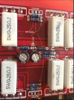
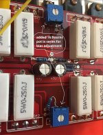
There's a d669 in between the OP devices that I suspect was part of the bias circuit. Hooked to it,s base is a 2.2k resistance. I lifted its leg going to the base of the d669 and inserted a 1k pot between them. Essentially allowing me to change the value of the 2.2k, from 2.2k to 3.2k. Increasing resistance adds or creates bias...
finally
Setting it to about 540hms (i.e. 2.2k becomes roughly 2.74k) and the amp is producing bias voltage across the 0.25ohm ER's.
Using Self's numbers to bias, I set each ER to have about 23.5mV across it or 47mV across both PNP/NPN emitters. This has brought this amp to life!
Low level sounds are well defined, there is bloom in the sound as well as slam. Much better definition and less listener fatigue. After 10 minutes, the heatsinks settle at 44C, but the bias drifts to 50mV across both ER's or 25mv across each one.
I need to spend more time ensuring that the 669 will regulate the bias since its mounted on the same heatsink, however this will need experimentation.
Also, the 2.7k setting is for 60vdc rails, once I get it to its final 82 (or 90) vdc, The amp will need to be rebiased.
At current bias levels, my calcs suggest its running about 2.6 watts class-A
Its a start, will report back on further tests.
A couple of pics where I inserted the pots:
I haven't looked lately, but are there integrated devices available now that have time alignment capabilities for reasonable cost? I know there are car head units with microphone inputs for that.
The amp has responded very well to some 8uf polycarbonate caps placed onto the main filter caps.
This is no doubt because of the lack of on board decoupling.
Also have added 47pf film caps onto the rca jacks, as well as a snubber arrangement onto the rectifier, both to a benefit.
Mounted the ( 450w njw 0302) kit on a heatsink currently on a smallish PSU running at 60v rails. Runs cold, it has zero bias...
sounds cold... too
I am working on getting some bias running through this amp...
There's a d669 in between the OP devices that I suspect was part of the bias circuit. Hooked to it,s base is a 2.2k resistance. I lifted its leg going to the base of the d669 and inserted a 1k pot between them. Essentially allowing me to change the value of the 2.2k, from 2.2k to 3.2k. Increasing resistance adds or creates bias...
finally
Setting it to about 540hms (i.e. 2.2k becomes roughly 2.74k) and the amp is producing bias voltage across the 0.25ohm ER's.
Using Self's numbers to bias, I set each ER to have about 23.5mV across it or 47mV across both PNP/NPN emitters. This has brought this amp to life!
Low level sounds are well defined, there is bloom in the sound as well as slam. Much better definition and less listener fatigue. After 10 minutes, the heatsinks settle at 44C, but the bias drifts to 50mV across both ER's or 25mv across each one.
I need to spend more time ensuring that the 669 will regulate the bias since its mounted on the same heatsink, however this will need experimentation.
Also, the 2.7k setting is for 60vdc rails, once I get it to its final 82 (or 90) vdc, The amp will need to be rebiased.
At current bias levels, my calcs suggest its running about 2.6 watts class-A
Its a start, will report back on further tests.
A couple of pics where I inserted the pots:
Attachments
Last edited:
No problem, my amp is actually oriented the same way currently, thanks for sharing.
I chose the 10uf input caps as it was the same value as what it came with, and I had a pair laying around. It would probably do well with half of that, but I don't really know what the input resistance is anyways. Suppose I could simulate the circuit.
I chose the 10uf input caps as it was the same value as what it came with, and I had a pair laying around. It would probably do well with half of that, but I don't really know what the input resistance is anyways. Suppose I could simulate the circuit.
I had a crappy polarized electrolytic on the input. 4.7 uF. Replaced it with a 0.5uF wima mkp I had. Sounds fine on a pair of baby Advents with a 5" woofer.
Many of the values of this amp are similar to the adcom gfa555mk2, which had a 1 uF on the input. Will do some tests in a couple of days to see if this will be ok or not.
With these two mods, theres a huge improvement in sound.
Many of the values of this amp are similar to the adcom gfa555mk2, which had a 1 uF on the input. Will do some tests in a couple of days to see if this will be ok or not.
With these two mods, theres a huge improvement in sound.
I wound up with some 100uf on the supplies as they entered the board, and some k71-5 Russian polystyrene.01 on the board next to the drivers. Nothing will wake it up like a little bias though, am sure that will make a it difference.
Am looking forward to hearing what you come up with, funny that it may be a copy of an old adcom...
Am looking forward to hearing what you come up with, funny that it may be a copy of an old adcom...
Did some calcs based on Andrew's 80ms constant and found, based on the 8k input impedance (3.3k in series with input plus 4.7k from there to ground) my initial 0.5uF was giving me a LF cut-off of about 40Hz. :-D
An order of caps came in today, and it had the WIMA mkc4's I ordered. 100v/ 3.3uF. Installed those, and now my F @ -3db should be around 6Hz. Which is fine...
Was building my capacitor bank today... not good at metal cutting, so took the whole day rigging tiny buss bars to connect the caps. Hopefully tomorrow, I will test is at 82v rails, and bias it to about 2 watts class A. Lets see if the njw0302/0281's are fake or real")
An order of caps came in today, and it had the WIMA mkc4's I ordered. 100v/ 3.3uF. Installed those, and now my F @ -3db should be around 6Hz. Which is fine...
Was building my capacitor bank today... not good at metal cutting, so took the whole day rigging tiny buss bars to connect the caps. Hopefully tomorrow, I will test is at 82v rails, and bias it to about 2 watts class A. Lets see if the njw0302/0281's are fake or real
No, the input is much lower impedance on this guy. About 8k. The 555 was as u said 100k with a 10hz F -3db. The feedback resistor on both is about 22k. Both employ 3 stage EF post vas, with 4 150watt OP devices. There are some variations, but the capabilities of both amps given that I am using 555's toroids on these, will be quite comparable.
- Status
- This old topic is closed. If you want to reopen this topic, contact a moderator using the "Report Post" button.
- Home
- Amplifiers
- Solid State
- Ebay kit looks interesting. 300w @ 8 ohms dual channel