Hello ") The circuit below is just for a proof of concept, it's not an actual circuit. How would one go about to get a stable bias current? The emitter resistors along with the Vbe-multiplier will prevent thermal runaway, but the bias current still rises with an increase in temperature. Because of the use of micas and different thermal resistances, the Vbe-multiplier BJT will unavoidable have a lower temperature than the other two bjts. I was thinking if there might be a way to use some kind of op-amp circuit or some transistor configuration to get the bias current to stay stable regardless of condition? Is that a lot to ask for?
The circuit below is just for a proof of concept, it's not an actual circuit. How would one go about to get a stable bias current? The emitter resistors along with the Vbe-multiplier will prevent thermal runaway, but the bias current still rises with an increase in temperature. Because of the use of micas and different thermal resistances, the Vbe-multiplier BJT will unavoidable have a lower temperature than the other two bjts. I was thinking if there might be a way to use some kind of op-amp circuit or some transistor configuration to get the bias current to stay stable regardless of condition? Is that a lot to ask for?
The circuit below is just for a proof of concept, it's not an actual circuit. How would one go about to get a stable bias current? The emitter resistors along with the Vbe-multiplier will prevent thermal runaway, but the bias current still rises with an increase in temperature. Because of the use of micas and different thermal resistances, the Vbe-multiplier BJT will unavoidable have a lower temperature than the other two bjts. I was thinking if there might be a way to use some kind of op-amp circuit or some transistor configuration to get the bias current to stay stable regardless of condition? Is that a lot to ask for? An externally hosted image should be here but it was not working when we last tested it.
Last edited:
One possible high cost improvement is to use the built in diodes of thermal trak transistors to sense the temperature of the output transistors. Two pairs of these are the NJL3281/1302 and the NJL4281/4302. Sanyo has some too but they are hard to find here and I don't have the numbers. The diodes are in the same package but not actually on the same die, I believe I've read.
You can first approximation put the diodes in series place of your MJE3055 sense transistor. Or you can use various op amp circuits to increase the response. I believe I read here D Self developed a patented circuit for using the sense diodes to drive opto-isolators to move the voltage around to the right place and correct any other deficiencies in modeling.
For more opinions search for "thermal-trak" to see various circuits including them. I have some LME49810 amp driver IC's that use these direct, but these were discontinued last year. You have to use surplus houses to buy these anymore, at your own risk.
Last edited:
but the bias current still rises with an increase in temperature
Of course, bias current regulates idle heat dissipation, if current will stay unchanged then you would need to regulate rails voltage.
The 'Thermal-trak' solution seems feasible, it should perhaps be able to completely compensate for the temperature drift if a proper circuit is made, right? They are expensive though
Is there a way to increase the thermal coefficient of my Vbe-multiplier in the circuit in my first post? What if I replace it with a darlington pair or something like that? I'm thinking of a way to make the voltage drop of the Vbe-multiplier increase more rapidly because of temperature change than the other two transistors.
Is there a way to increase the thermal coefficient of my Vbe-multiplier in the circuit in my first post? What if I replace it with a darlington pair or something like that? I'm thinking of a way to make the voltage drop of the Vbe-multiplier increase more rapidly because of temperature change than the other two transistors.
Is there a way to increase the thermal coefficient of my Vbe-multiplier in the circuit in my first post?
You can change output transistors to MOSFETs, this will demand increasing of Vbe-multiplier output voltage, so regulation will be more sensitive.

Bias transistors can be in SOT-23 something like BC850/860 placed straightly near output MOSFET legs.
Basic calculation needs to include idle heat dissipation, bias regulation depth around working 20-70 degrees temperature, and estimated dissipation due to load currents.
Your bias regulation depth must provide decreasing of idle dissipation at least to factor of 1,5-2 of estimated dissipation from load current.
Don't forget output current phase due to reactive load.
Your circuit is basically right, but you must improve some components or values.
Vbe multiplier resistors must pass 10 to 5X bias transistor idle current so it remains basically "voltage controlled" .
Your values are way too high, and to boot you need to reach "two diode drops" across bias transistor to just turn on two power transistor BE junctures.
Re- simulate with , say, 1k R4-R5 instead of current 50k-100k and you´ll find better results.
2) a large power transistor is not the best choice for a thermal compensator, specially because of very poor Hfe at low current, a regular low signal one is way better (Hfe easily spanning 100-500X at 10 mA).
Sometimes and only because of mounting convenience, a TO220 type one is used as a compromise.
3) if it´s properly attached to the heatsink it does track temperature reasonably well.
If the collector base resistor of the vbe multiplier is replaced by a thermistor/ resistor combination you can increase the effectiveness of the compensation
2 if you are feeding the vbe multiplier from a constant current source you can also use this to improve the thermal tracking ie the base vbe reference diodes on the constant current source can also be made to track the heatsink temperature in this way you can over compensate
Trev
2 if you are feeding the vbe multiplier from a constant current source you can also use this to improve the thermal tracking ie the base vbe reference diodes on the constant current source can also be made to track the heatsink temperature in this way you can over compensate
Trev
2) a large power transistor is not the best choice for a thermal compensator, specially because of very poor Hfe at low current, a regular low signal one is way better (Hfe easily spanning 100-500X at 10 mA).
Sometimes and only because of mounting convenience, a TO220 type one is used as a compromise.
What type of transistor would you recommend? I'm not sure what parameters to search for when looking for high Hfe at low collector current.
Also. What if I replace the whole Vbe-multiplier with a thermistor and resistor in series? By adjusting the values of those two resistors I should be able to get whatever temperature compensation I want, no?
Last edited:
read post7
and read it again !
I have used sot23 as well as To92 both work well, but I think the sot23 glued to the output device centre lead is quicker and as a result more accurate.
I did as you said and I did get much better results. Can I reduce the Vbe-multiplier resistors even more? Even though if were to get perfect temperature compensation, it's still hard to adjust the bias current as one small touch on the potentiometer adjusting the Vbe-multiplier voltage will cause huge changes in the bias current. One way to avoid this is to reduce the Vbe-mulitplier resistors to 100-200 Ohms
How is it practical to glue a SOT-23 to the leg the power transistor? How will the SOT-23 itself be soldered to the PCB?
Is it possible to find a solution that directly senses the bias current and adjusts accordingly? The circuit below keeps the bias current stable at all conditions, it only works as long as you don't amplify anything so I guess it will be suitable as an oven if the dissipation is high enough. I'm just trying to show an idea
An externally hosted image should be here but it was not working when we last tested it.
Yes, nulling out the speaker current is generally a bad idea. Ha!The circuit below keeps the bias current stable at all conditions, it only works as long as you don't amplify anything so I guess it will be suitable as an oven if the dissipation is high enough. I'm just trying to show an idea
An additional quibble, op amps that will take +-25 v supplies tend to cost >$6 like the LM675 or LTC6090.
Glueing transistors on other transistors, there are thermal compounds sold that contain epoxy.
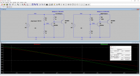
You can adjust the tempco of a Vbe multiplier by changing the current that runs through the first transistor. In the case shown here, going from R1=1K on the left ot R6=100K on the right. There are two factors at work:
1. the tempco of Vbe=(Vbe-Vgo)/T (Vgo is the bandgap voltage of silicon, about 1.21 volts, T is temp in Kelvin), so a transistor operating at lower current, and hence lower Vbe has a more negative tempco.
2. To make up for that lower Vbe, and make both circuits have the same voltage at around 25C, we need to increase the multiplier ratio (R3/R2 or R5/R4), which also increases the tempco
The result is that the circuit on the left has -7.55 mV/C, and on the right we have -10.05 mV/C.
That difference is pretty large...over a 20C change, that makes a (10.05-7.55)*20=50 mV difference. Across the typical 0.54 Ohms of total emitter resistance (0.27+0.27), that current difference would be 50 mV/0.54 Ohms = 92.6 mA in quiescent current.
Attachments
Last edited:
You can also add a voltage source like I did in my honey badger build to get a lower tempco: link
I am also thinking about a better approach of bias stabilization. My idea is to use a microcontroller measuring the bias current at zero crossing (AD is triggered by zero crossing).
I am also thinking about a better approach of bias stabilization. My idea is to use a microcontroller measuring the bias current at zero crossing (AD is triggered by zero crossing).
I looked at this issue in some depth a few years ago and captured my thoughts at the time here
Some Ideas on Temperature Compensation for Audio Amplifier EF Triples
I have ended up using a two transistor solution similar to that proposed by Daniel Joffe on my power amps.
I use a BC847 which I mount close to the collector lead of one of the output power devices. More recently, I place 4 or 5 of these devices in parallel around the output stage and then during development selecting the one that provides the best bias compensation - only one being connected at a time of course. Its pretty easy I have found to quickly home in on the best sensor position this way. I have also used an NTC (see 'E-Amp' on my website for a practical example) to augment the temp comp ('two point thermal comp') that also works very well.
re using a microcontroller - best approach here probably is to use the standard two transistor scheme for 1st order compensation and then let the controller do the 2nd order compensation. You can also then make the system self calibrating with a bit more effort provided you can store the correction coefficients easily in memory. There are a few very nice 8pin controllers with 8-10 bit A-D's - you will only need 3 or 4 bits for effective correction.
Would it be possible with some kind of comparator solution? A comparator that measures the voltage across a sense resistor and then outputs into an optocoupler perhaps. The comparator will ram violently up and down when the amplifier is amplifying something though, but if its passed through a low-pass filter, the duty cycle should correspond to the wanted bias current. I haven't simulated this, I'm probably forgetting something crucial, but you get the idea I hope?
LT 1166
check out this chip:
Linear Technology LT1166
check out this chip:
Linear Technology LT1166
Would it be possible with some kind of comparator solution? A comparator that measures the voltage across a sense resistor and then outputs into an optocoupler perhaps. The comparator will ram violently up and down when the amplifier is amplifying something though, but if its passed through a low-pass filter, the duty cycle should correspond to the wanted bias current. I haven't simulated this, I'm probably forgetting something crucial, but you get the idea I hope?
Many, many amps use BD139 for the Vbe multiplier. It has very good tracking if set up correctly. It also has a bolt hole to boot so you can mount it directly on top of one of the outputs as a washer with flying leads. Or mount directly to heatsink near one or both outputs.
- Status
- This old topic is closed. If you want to reopen this topic, contact a moderator using the "Report Post" button.
- Home
- Amplifiers
- Solid State
- How do I get a stable bias current?