Thanks Toni,i have thermal paste on hand but i see silicone pads 0.5mm or 1mm thickness that would be more ideal.You could use silicon instead of your thermal grease too. You heatspreader is 10mm thick and is many times greater as your transistors surface.
Of course a possibility: 2-3 mm deep hole should be enough. Fill it with a little bit thermal grease. Or just add a squishy spacer between pcb and BC550C as AndrewT has done.
The red LED need not to be in direct thermal contact with the heatsink - only between pcb and heatspreader.
BR, Toni
The red LED need not to be in direct thermal contact with the heatsink - only between pcb and heatspreader.
BR, Toni
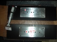
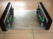
The heat spreader drilled using 6mm drill for the center and 10mm for the top.I'm sure it will do its coooooling!")
The heatsink drilled using 3.5mm then 4mm and tapped with a 5mm, sharpened to the lower end,tapping tool.
Screws are 5x12mm inox .
All parts cleaned using dish washer liquid for tapping fluid removing.
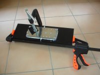
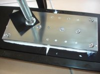
After drying a plenty of thermal paste applied
Aluminum was pressed as in the picture to reduce the gaps to the minimum.
Finally the screws tightened.
Last edited:
Hello Thimios
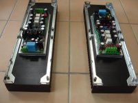
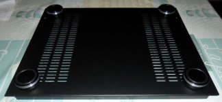
I see that you have positioned the plate with the holes as I told you. With this layout you will not have to drill the bottom of the case, just for the feet.
Congratulations for your work and I think you will really have no problem with heat dissipation.
Regard's
I see that you have positioned the plate with the holes as I told you. With this layout you will not have to drill the bottom of the case, just for the feet.
Congratulations for your work and I think you will really have no problem with heat dissipation.
Regard's
Attachments

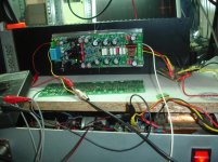
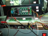
Analytical thermal condition.Perfect cooling!
BR, Toni
Power supply=+/-42V
Idle current=150mA/pair
Mixed operating cycle, high volume, low volume,no out.
Maybe i need better quality transistor insulators?
Attachments
Last edited:
Never mind,i think yes and yes.Hello astx
This amplifier interests me (I do not know yet which version) but can this be suitable with only 2 pairs of hexfets by lowering the supply voltage?
Thank you
PS: Thimios, I'm sorry to ask my question on your thread.
Toni has designed many different versions.
You must wait for his answer.
Last edited:
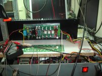
Analytical thermal condition.
Power supply=+/-42V
Idle current=150mA/pair
Mixed operating cycle, high volume, low volume,no out.
Maybe i need better quality transistor insulators?
What have you used as isolators? I've used keratherm red ... (conrad)
Test it with high continuous output power for several minutes to see how the temperature rises. Stop tests if going too fast above 60 degrees.
But looks good so far. (Bias idle current produces 38W dissipation! You have more as one class A watts for listening).
The MCU board has connections for 3 NTC resistors. If you are finishing the assembling of your amplifier add one NTC at each heatsink and one in the internal middle of your amplifier.
BR, Toni
...
This amplifier interests me (I do not know yet which version) but can this be suitable with only 2 pairs of hexfets by lowering the supply voltage?
...
SA2015 using IRFP240/IRFP9240 should work with 2 pairs too when you lower the rail voltages. If you drive only 8R loads you can safely omit 1 pair of MOSFETs.
BR, Toni
Silicone Rubber gray color together with thermal paste.What have you used as isolators? I've used keratherm red ... (conrad)
Test it with high continuous output power for several minutes to see how the temperature rises. Stop tests if going too fast above 60 degrees.
But looks good so far. (Bias idle current produces 38W dissipation! You have more as one class A watts for listening).
The MCU board has connections for 3 NTC resistors. If you are finishing the assembling of your amplifier add one NTC at each heatsink and one in the internal middle of your amplifier.
BR, Toni
Unfortunately keratherm aren't available here.
Test it with high continuous output power for several minutes to see how the temperature rises. Stop tests if going too fast above 60 degrees.
60°c, where i must take this measurement?on the main heatsink or direct on transistors body?
Last edited:
Silicone Rubber gray color together with thermal paste.
mmm, pretty sure you shouldn't use thermal paste with silicone pads
I'm pretty sure you are right.mmm, pretty sure you shouldn't use thermal paste with silicone pads
I amn't sure what is the right,i see many commercial products using rubbers+paste,other not.I'm pretty sure you are right.
I will try to measure in my SX(Bonsai) amplifier where rubbers and no paste has been used.
- Status
- This old topic is closed. If you want to reopen this topic, contact a moderator using the "Report Post" button.
- Home
- Amplifiers
- Solid State
- SA2015 V-MOSFET Builders