I was wondering if some of the seasoned veterans around here could give me some comments on this design. What I am shooting for is about 10-15W class A and as simple as I could get it. Biasing the IRF540 pairs to 2A should get me there.
The power rail caps on the opamp were omitted for 'clarity'. Would I need to put filter networks on the bias and offset circuits even though I will be using regulated voltages (LM317/337)? Any comments or suggestions would be greatly appreciated.
Thank you,
SteveS
The power rail caps on the opamp were omitted for 'clarity'. Would I need to put filter networks on the bias and offset circuits even though I will be using regulated voltages (LM317/337)? Any comments or suggestions would be greatly appreciated.
Thank you,
SteveS
Attachments
jam:
I must admit most of the inspiration for this design is from Monarchy's SE-70 amplifier. It too does not include the OP stage in the feedback loop and from what I'v read this give a touch more openess to the sound. I'm not a big fan of using feedback, so I thought why not give it a try. The SE-70 however uses a push-pull OP stage biased to class A.
tschrama:
The reasons for the dual power supply are:
1. I wanted a clean voltage source for running the opamp and biasing (input stage and current source).
2. I have a trasformer with multiple taps to accomodate.
3. It will give me more voltage output from the opamp to compensate for Vgs.
However, if you (or anyone else) has a good idea on a circuit to provide 23V from the unregulated legs I'm all ears.
Thank you,
SteveS
ClassA
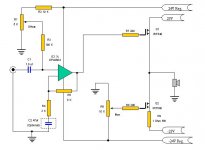
C1 1uF and R1 1Meg make the gain unity at DC and R4/R3 at audio frequencies
R6 and C3 filter RF out of input.
D1 and R9 set the bias current for output stage. Look at data sheet and or test for the gate to source voltage of mosfet at 2 amps. Zener voltage will equal Vgs+(2ampsXR9). Stay above 1 ohm for R9 for good thermal stability. Don't forget to test well before hooking up speaker. I would fuse 23 volts rails with 6 amp quick acting fuses.
H.H.
You can reduce +Vs for Q1, as there is always a voltage difference of some 4V between Gate and Source of the Q1. The circuit of current source Q2 might be a bit dangerous if done as shown. R6 bottom end should be connected to -Vs (-23V) of Q2. Then constant current will be: Ic = (Ubias - 4V)/R9.
- Status
- This old topic is closed. If you want to reopen this topic, contact a moderator using the "Report Post" button.
- Home
- Amplifiers
- Solid State
- 15W SE amplifier schematic