Whats the diffrence between high and low voltage ampfliers, typically talking about the output transistors. In this talk we assume the voltage amplification stage does not change in terms of gain and perfomance+distortion.
As the current entering the node has to equal to current leaving the node, increacing the voltage will not decrease the current for outputing 1V into 8ohms.
Not only circuit theory tells me this but the circuit simulator also says the samething.
So if higher voltage transistor have to give out the same ammount of current to give out the same power to the speaker, whats the adavantage of having a high voltage supply for the outputs. Does it decrease distortion?
This means a 50v amp will dump twice the ammount of power when outputing 1v ac into 8ohms. Compared to a 25V amp.
I know higher operating voltages means that transistors have a lower output cappacitance but I would like if we neglect the effects of output capacitance during this talk.
Also can we ignore the fact that you can get higher peak to peak voltages with higher supply voltage for this talk.
I want to know more about high voltage outputs compared to low voltage. If high voltage outputs are pointless this means I can undervolt my class a AMP and increacse my bias current further
Last edited:
Things do not go as said.
Assuming an 8 ohm load the rail voltages are directed by the max power you want from the amplifier.
With + 40v -40v rails, the peak current is 5A, hence peak power 200W So the amp can provide 100W RMS.
Actually a bit less because of some voltage drops and distortion near clipping.
Assuming an 8 ohm load the rail voltages are directed by the max power you want from the amplifier.
With + 40v -40v rails, the peak current is 5A, hence peak power 200W So the amp can provide 100W RMS.
Actually a bit less because of some voltage drops and distortion near clipping.
Many of the transistors in a Power Amplifier need to be voltage rated to exceed the sum of the supply rails voltages.
A typical 100W into 8ohms amplifier will have supply rails of ~ +-50Vdc
That requires many of the transisteors to be rated at over 100Vceo
Now go and look at medium power and high power BJT transistors.
Select some 100Vceo devices and compare to 160Vceo and to 250Vceo devices.
note the BIG difference in SOA @ 50 and 80Vce operating voltages.
It's the loss in SOA @ operating voltage much above half their Maximum Vceo that rules 100Vceo devices from being used in 100W amplifiers.
As I said in the opening of the thread.
Can we ignore the fact that you can get higher peak to peak voltages (more power) with higher supply voltage for this talk.
All I want to know is in terms of sound quality and distortion, on having high voltage current gain stage vs low current gain stage.
Can we ignore the fact that you can get higher peak to peak voltages (more power) with higher supply voltage for this talk.
All I want to know is in terms of sound quality and distortion, on having high voltage current gain stage vs low current gain stage.
If you blow up your amplifier it will produce absolutely Zero THD. Does that make it good on a Sound Quality basis?As I said in the opening of the thread.
Can we ignore the fact that you can get higher peak to peak voltages (more power) with higher supply voltage for this talk.
All I want to know is in terms of sound quality and distortion, on having high voltage current gain stage vs low current gain stage.
High voltage is more useful for 8 ohms speakers than 4 ohms speakers.
8 ohms was universal in the early 70's, then the cost of alnico dropped a lot, so magnets got stronger. (patent expiration perhaps?) Number of turns of wire could be reduced for the same force on the cone. Late 70's early 80's a lot of 4 ohms speakers were produced. Watts ratings were higher at 4 ohms than 8 with the same number of parts, so amp manufacturers started rating at that and selling for that. Rail voltages dropped.
In addition to lower normal rail voltage, 1966-1972 power transistor gains were very low at significant current, an amp or higher. Think of what low gain does to the cost with heatsinks on higher current driver transistors. So one pair OT 60 W/ch amps were 70v rail (leak & dynaco). Not necessary now. More power became available with parts like 2n3773, MJ802 etc.
The publication of the soa rating for transistors made the cause of mysterious failures a lot more obvious, so the design could run a lot closer to the limit without driving up warrenty costs. Mid 80's perhaps?
As far as voltage limit on the transistors, look at the test conditions. It became normal to test power transistors at 50 ma on the Vceo test, which current no designer in his right mind would leave a transistor leaking at idle. Previous test condition was 10 ma. So voltage ratings on datasheets became rather silly IMHO, whereas soa ratings could be used for design.
HD ratings normal are different for different markets. So some amps were rated at 1% HD, with a little clipping allowed. Other amps were rated at .00x% HD and need a little more voltage to achieve that with no clipping. Different markets will lead to different rail voltages for same wattage, with the desire for minimum production cost of course driving all the successful businesses. The installation of heat sinks on driver transistors adds $$ assembly costs, so most amps you see in receivers etc don't have them - the consumer market. Amps with 24/7 ratings, PA amps, tend to have them. How much heat your drivers will shed drives your rail voltage somewhat.
Last edited:
Answering you literally:
* if you want to put 1 V RMS into an 8 ohm speaker, you can probably do it with a +/-3V supply.
* if you now power same amp with, say, +/-25V , but still put out 1V RMS into the same speaker:
a) distortion will not change
b) dissipation will increase
So under your very limited requirements , "high voltage supply is worse than low voltage supply"
I should ask, though, but I won´t: is 0.125W RMS (1V RMS into 8 ohms) enough for your Music reproduction needs?
No need to answer.
"I want to know more about high voltage outputs compared to low voltage. If high voltage outputs are pointless this means I can undervolt my class a AMP and increacse my bias current further "
http://www.diyaudio.com/forums/solid-state/40355-grahams-class-jlh-output.html
Please see the above thread. Some interesting info about higher than minimum necessary Voltage supplies.
http://www.diyaudio.com/forums/solid-state/40355-grahams-class-jlh-output.html
Please see the above thread. Some interesting info about higher than minimum necessary Voltage supplies.
The OP is just seeking confirmation for the idea that changing the supply voltage won't affect sound quality. His question (focused down in #5) is a nebulous one about the subjective sound effects/benefits of using high or low voltage rails in a class A amplifier regardless of other implicit differences.
Class A amplifiers struggle to have enough power for realistic sound levels. That's why full class A systems are huge and expensive room heaters and the OP is trying to avoid this by using lower supply voltages. That's really the same class A issue brought up many times - i.e. "can I have class A sound quality without so much heat and power?"
In my limited experience, as long as the relative amplifier noise levels and linearity remain the same and it never clips (hard to avoid with low voltage rails) there is no single reason that a particular amplifier should sound better or worse within its possible range of supply voltage rails. However, if it requires a lower volume level to stay within the limits of clipping, it will certainly sound different - since perceived sound quality and volume are inter-dependent.
However, I don't think it is wise to simply change the supply voltages of any particular power amplifier - better to start anew with a lower powered and lower cost model that already has lower supply rails by design and likely makes more efficient use of them.
If you have already done something like buying an amplifier or kit of parts and now want to modify it, it would be better to see what you are considering first before making generalised comments that may not address the real issues.
I would rather prefer higher supply voltage for two reasons. Todays powerfull speakers (especially these with high Qms) have very high impedance peaks, and with lower tuning, they might have some dip in frequency response compared to more conventional designs (with higher Qts). So you need to straighten your FR, but it is hard when the speaker "lurks around" 100Ohm mark at these frequencies. You need enaugh voltage sving to put the power there.
Second thing goes along. Dynamic range. If you listen to music with higher DR, you may need 100W amp to enjoy, and 1000W for louder production. With speaker resistance in mind, you'll need high voltage to do that.
Second thing goes along. Dynamic range. If you listen to music with higher DR, you may need 100W amp to enjoy, and 1000W for louder production. With speaker resistance in mind, you'll need high voltage to do that.
All I want to know is in terms of sound quality and distortion, on having high voltage current gain stage vs low current gain stage.
I think this is difficult to answer. It will depend on the exact situation/implementation and also on your subjective taste/preference.
Lets assume that your target is 10 W. Some people will swear that whatever you do (adding more current into class A) it will never sound good enough. Some other will swear the opposite. It is because the amps you are comparing are indeed different and people priority, sensitivity to sound performance is different.
For most people and you included i would assume that higher current tends to be better than higher voltage (no current limitation here). If it is at all possible to draw such line. For me it would depend mostly on the transistor used. Ouput quality is a function of 3 things: (1) the driving stage that we have assumed irrelevant for the sake of discussion simplicity, (2) the speaker that unfortunately we tend to assume irrelevant by modelling a resistive load and mistakenly think that speaker distortion is constant and (3) the performance of the output transistor at different operating conditions (V and I).
I have never designed a current-no-object amplifier. If i want to build one then i will start to look for my preferred hexfet, not bipolar or latfet i guess. And when i find the transistor i will give it its preferred current (for class B i think voltage is more critical).
So you see, for me, currentnoobject or not, i will go with the best current for the output transistor. (Some hexfets requires extreme current to combat the highizh capacitance, some bjt requires below 1 ampere).
Last edited:
You must ensure the outputs have sufficient temperature de-rated SOA to survive.................. and its better to have lower voltage outputs with higher bias current.............
That often means using HIGH voltage outputs.
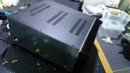
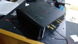
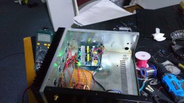
Rebuilt +-50v amp to +-24v Class A
As promised I will let you know if I modd my amp
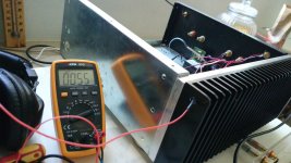
Idles at about 2.5Amps, maximum output voltage is about 40-44v pk-pk without any distrotion or clipping, very clean and crisp.
The amp outputs in excess of 50W peak power (25w rms)
Because the amp operates in super class a(idle current dosen't change) up untill very near clipping.
Very loud music on 15 inch sounds much better than before, overall sound quality improved.
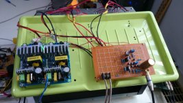
In the new circuit, there were a few refinements made to the circuit, and it has been redesigned to run on duall 24 volts.
No input or output caps, pure ocl.
I also kept my orignal pcb that operates on 2x50v so I can revert anytime if I want, thats why the new amp was built on a project board
As promised I will let you know if I modd my amp
Idles at about 2.5Amps, maximum output voltage is about 40-44v pk-pk without any distrotion or clipping, very clean and crisp.
The amp outputs in excess of 50W peak power (25w rms)
Because the amp operates in super class a(idle current dosen't change) up untill very near clipping.
Very loud music on 15 inch sounds much better than before, overall sound quality improved.
In the new circuit, there were a few refinements made to the circuit, and it has been redesigned to run on duall 24 volts.
No input or output caps, pure ocl.
I also kept my orignal pcb that operates on 2x50v so I can revert anytime if I want, thats why the new amp was built on a project board
Attachments
-
 DI1x6NIVYAAUQ0Y.jpg93.3 KB · Views: 440
 -
 DI1x21fVAAEkTfw.jpg113.4 KB · Views: 442
 -
 DI1xfzDVoAAAd0v.jpg147.2 KB · Views: 438
 -
 DIxMxUTUMAEcQPr.jpg153.4 KB · Views: 429
 -
 DIxo_6lVYAEdddr.jpg142.8 KB · Views: 452
 -
 DIxpEATUEAAEK59.jpg165.5 KB · Views: 143
 -
 DIxpFh-VAAQOxLz.jpg135.2 KB · Views: 148
 -
 DIxpG8XUIAAuqXz.jpg164.8 KB · Views: 188
 -
 DIxpKI4VoAAocTq.jpg143.6 KB · Views: 207
 -
 DIrgkJqV4AAui_d.jpg147.8 KB · Views: 213
It is best to design with the right voltage level and quiescent bias to match the expected load. For Class A these have to go together; too little current means early clipping, too much current means overheating. For Class B they can be considered somewhat separately.SMY14INCH said:Hey guys thanks for the response, I may want to conclude that change in supply voltage dosen't effect sound quality and its better to have lower voltage outputs with higher bias current.
No, that is Class A.SMY14INCH said:Because the amp operates in super class a(idle current dosen't change) up untill very near clipping.
Caps do useful stuff, which is why they were invented.No input or output caps, pure ocl.
explain why it is not Class A.
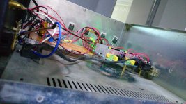
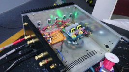
Clearly mine is Class A, it idles at about 2.5Amps, when music is playing current dosen't change, right up untill near clipping when driving a 100W low sensitivity speaker for testing purpourses.
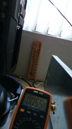
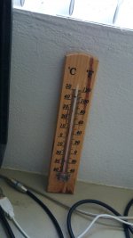
The heat sink is 3.4KGS and you can see in pic 55C at approx 15 c room temp.
thats 120w of power consumed at idle.
I want to say caps do nothing but distortion, you put ac voltage through caps, theres phase shift and dilectric losses and all kinds of distrtion, a copper conductor direct input to a fet is always less lossly than a cacpacitor input.
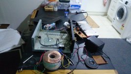
If PCB are used, then resistance from transistors to transistor varies. with wires used, all resistance can be equal and the effective resistance would be lower than on a pcb without added copper tracks
Each wire used can take in excess of 5 amps, approx 8amps no plorbem can do 10amps warm.
With the orignal pcb for the amp it is impossible to have equal emitter and collector resistance for all transistors at output stage
Clearly mine is Class A, it idles at about 2.5Amps, when music is playing current dosen't change, right up untill near clipping when driving a 100W low sensitivity speaker for testing purpourses.
The heat sink is 3.4KGS and you can see in pic 55C at approx 15 c room temp.
thats 120w of power consumed at idle.
I want to say caps do nothing but distortion, you put ac voltage through caps, theres phase shift and dilectric losses and all kinds of distrtion, a copper conductor direct input to a fet is always less lossly than a cacpacitor input.
No they are not and they all share the load nearly equaly. Wires are all same lengthAll bets are off with the length of those wires to the transistors...
If PCB are used, then resistance from transistors to transistor varies. with wires used, all resistance can be equal and the effective resistance would be lower than on a pcb without added copper tracks
Each wire used can take in excess of 5 amps, approx 8amps no plorbem can do 10amps warm.
With the orignal pcb for the amp it is impossible to have equal emitter and collector resistance for all transistors at output stage
Last edited:
Amplifiers with flying wires are far more likely to misbehave than ones without them. You may get lucky, you may not. You may equalize the resistances, but now have a lot of unnecessary inductances - including the mutual kind.
Even if the amplifier does not oscillate, you will have nowhere near the distortion and noise capability that the circuit could otherwise have. With a simple circuit, and class A operation you may get away with it. But you later go to build something bigger the same way and it doesn't work. Then you'll be back here asking why.
Even if the amplifier does not oscillate, you will have nowhere near the distortion and noise capability that the circuit could otherwise have. With a simple circuit, and class A operation you may get away with it. But you later go to build something bigger the same way and it doesn't work. Then you'll be back here asking why.
No, that is Class A.
I thought you said my amp wasn't class A but apprently that wasn't the case.
Wasn't awake this morning when I did the reply
What I was implying with the idle current is that it dosen't need to increace right up to near clipping, for a 40v pk-pk the current through transistors required are about 2.5amps, i'm idling somewhere at 2.5amps.
Class a means half of maximum current when driving a speaker, whats happening here is little bit more extreme than class a so i called it super class a.
Thanks for the tip, but in my point of view, then noise picked up from the wire is negible and low same with inductance.Amplifiers with flying wires are far more likely to misbehave than ones without them. You may get lucky, you may not. You may equalize the resistances, but now have a lot of unnecessary inductances - including the mutual kind.
Even if the amplifier does not oscillate, you will have nowhere near the distortion and noise capability that the circuit could otherwise have. With a simple circuit, and class A operation you may get away with it. But you later go to build something bigger the same way and it doesn't work. Then you'll be back here asking why.
Last edited:
- Status
- This old topic is closed. If you want to reopen this topic, contact a moderator using the "Report Post" button.
- Home
- Amplifiers
- Solid State
- PROS? High Voltage VS Low Voltage Amp