Hi everybody,
This is my latest DIY and IMHO, with the right speakers, is also one of the finest sounding amplifiers for the DIY hobbyists.
Thanks for JLH.
It is JLH 1969 single supply.
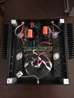
I built the circuit point-to-point on four double sided fiberglass perfboards, two for capacitance multiplier and two for signal circuits.
Transformer is toroidal 300VA 2 x 18V.
Capacitance multiplier is exactly Rod Elliott’s recommended circuit.
No noise, no hum, one of the most silent amplifiers that I used but keep in mind that I am mostly into tubes.
The only drawback with Capacitance multiplier is voltage drop. With the same transformer for Gainclone etc..I usually get 24V-25V B+ with CRC Power Supply. Now B+ is 22V with Capacitance Multiplier.
Transistors are modern versions;
BC560 for input, 2N1711 for driver and MJ15003G for output.
Capacitance Multiplier transistors are BD139 and TIP35
All signal board electrolytic capacitors are Elna Silmic II, output bypass and zobel caps are Vishay MKP1837. Input caps are Orange Drop 716P.
All PS electrolytic capacitors are Panasonic 105oC.
With 22V B+ and 1.45Amps bias, I am guessing around 7 Watt output.
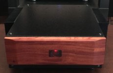
The case is my old tube preamp case, I rebuilt it and drilled many holes etc..Paint is electrostatic with some granules or particules in it (sorry I don’t know the terminology of this paint).
Front is natural Rosewood.
I chose this version for originality, simplicity and speaker DC protection by output capacitors.
I am using it in my secondary system with New Large Advents. I also tried it in my main system with Triangle Octant dipoles.
It is like Denon DL103 cartridge of amplifiers.Full bass FQ, big, bold and a little bit warm sounding but also naturally detailed and dynamic.Also spatially good.
It is also relatively inexpensive to build and if you have highly efficient speakers with benign load an excellent amplifier to live with.
Now it is time to complete First Watt F6 project until summer.
Regards,
Hakan
PS:I don’t know if it’s because using modern high FQ transistors or not, at first, amplifier oscillated a bit, especially with the tube preamp.
Then, I put Zobel 100nF + 10R and 2uH coil parallel to 10R at the output.Plus Low pass filter in addition to input cap + R(high pass).
Now amplifier is stable with my any preamp (passive or active) and speakers.
For this one, many thanks to AndrewT for his writings on this subject.
This is my latest DIY and IMHO, with the right speakers, is also one of the finest sounding amplifiers for the DIY hobbyists.
Thanks for JLH.
It is JLH 1969 single supply.
I built the circuit point-to-point on four double sided fiberglass perfboards, two for capacitance multiplier and two for signal circuits.
Transformer is toroidal 300VA 2 x 18V.
Capacitance multiplier is exactly Rod Elliott’s recommended circuit.
No noise, no hum, one of the most silent amplifiers that I used but keep in mind that I am mostly into tubes.
The only drawback with Capacitance multiplier is voltage drop. With the same transformer for Gainclone etc..I usually get 24V-25V B+ with CRC Power Supply. Now B+ is 22V with Capacitance Multiplier.
Transistors are modern versions;
BC560 for input, 2N1711 for driver and MJ15003G for output.
Capacitance Multiplier transistors are BD139 and TIP35
All signal board electrolytic capacitors are Elna Silmic II, output bypass and zobel caps are Vishay MKP1837. Input caps are Orange Drop 716P.
All PS electrolytic capacitors are Panasonic 105oC.
With 22V B+ and 1.45Amps bias, I am guessing around 7 Watt output.
The case is my old tube preamp case, I rebuilt it and drilled many holes etc..Paint is electrostatic with some granules or particules in it (sorry I don’t know the terminology of this paint).
Front is natural Rosewood.
I chose this version for originality, simplicity and speaker DC protection by output capacitors.
I am using it in my secondary system with New Large Advents. I also tried it in my main system with Triangle Octant dipoles.
It is like Denon DL103 cartridge of amplifiers.Full bass FQ, big, bold and a little bit warm sounding but also naturally detailed and dynamic.Also spatially good.
It is also relatively inexpensive to build and if you have highly efficient speakers with benign load an excellent amplifier to live with.
Now it is time to complete First Watt F6 project until summer.
Regards,
Hakan
PS:I don’t know if it’s because using modern high FQ transistors or not, at first, amplifier oscillated a bit, especially with the tube preamp.
Then, I put Zobel 100nF + 10R and 2uH coil parallel to 10R at the output.Plus Low pass filter in addition to input cap + R(high pass).
Now amplifier is stable with my any preamp (passive or active) and speakers.
For this one, many thanks to AndrewT for his writings on this subject.
Attachments
Goodmorning everyone!
I'm back now working and I have found many questions: thanks for the interest.
First of all I have to disappoint some of your requests not being able to take and send photos with the computer (I'm pretty old and the photos I still do with the film, when I do) but I will try to copy and send the schema with the components as can easily find on the internet, hoping it will be enough.
However, I would at least look for an indication as to which could be the components most interested in the problem, as for example Mr. Gabardela suggested to check the nature of the cables having these their importance.
Actually I used the "special" cable (enamelled by 1mm2 with high temperature insulation) for the wiring of the power supply and the connection of the MJ15003 to the circuit board: this because it is aware of the rather high operating temperature and the sizing for continuous use I have considered essential to take appropriate measures.
Now I would be really incredulous in front of such a phenomenon, however ... I would like further clarification.
Thank you so much, now I see if I can attach the patterns ... greetings.
Mleod

Bingo!")
I'm back now working and I have found many questions: thanks for the interest.
First of all I have to disappoint some of your requests not being able to take and send photos with the computer (I'm pretty old and the photos I still do with the film, when I do) but I will try to copy and send the schema with the components as can easily find on the internet, hoping it will be enough.
However, I would at least look for an indication as to which could be the components most interested in the problem, as for example Mr. Gabardela suggested to check the nature of the cables having these their importance.
Actually I used the "special" cable (enamelled by 1mm2 with high temperature insulation) for the wiring of the power supply and the connection of the MJ15003 to the circuit board: this because it is aware of the rather high operating temperature and the sizing for continuous use I have considered essential to take appropriate measures.
Now I would be really incredulous in front of such a phenomenon, however ... I would like further clarification.
Thank you so much, now I see if I can attach the patterns ... greetings.
Mleod
Bingo!
Hi everybody,
This is my latest DIY and IMHO, with the right speakers, is also one of the finest sounding amplifiers for the DIY hobbyists.
Thanks for JLH.
It is JLH 1969 single supply.
I built the circuit point-to-point on four double sided fiberglass perfboards, two for capacitance multiplier and two for signal circuits.
Transformer is toroidal 300VA 2 x 18V.
Capacitance multiplier is exactly Rod Elliott’s recommended circuit.
No noise, no hum, one of the most silent amplifiers that I used but keep in mind that I am mostly into tubes.
The only drawback with Capacitance multiplier is voltage drop. With the same transformer for Gainclone etc..I usually get 24V-25V B+ with CRC Power Supply. Now B+ is 22V with Capacitance Multiplier.
Transistors are modern versions;
BC560 for input, 2N1711 for driver and MJ15003G for output.
Capacitance Multiplier transistors are BD139 and TIP35
All signal board electrolytic capacitors are Elna Silmic II, output bypass and zobel caps are Vishay MKP1837. Input caps are Orange Drop 716P.
All PS electrolytic capacitors are Panasonic 105oC.
With 22V B+ and 1.45Amps bias, I am guessing around 7 Watt output.
The case is my old tube preamp case, I rebuilt it and drilled many holes etc..Paint is electrostatic with some granules or particules in it (sorry I don’t know the terminology of this paint).
Front is natural Rosewood.
I chose this version for originality, simplicity and speaker DC protection by output capacitors.
I am using it in my secondary system with New Large Advents. I also tried it in my main system with Triangle Octant dipoles.
It is like Denon DL103 cartridge of amplifiers.Full bass FQ, big, bold and a little bit warm sounding but also naturally detailed and dynamic.Also spatially good.
It is also relatively inexpensive to build and if you have highly efficient speakers with benign load an excellent amplifier to live with.
Now it is time to complete First Watt F6 project until summer.
Regards,
Hakan
PS:I don’t know if it’s because using modern high FQ transistors or not, at first, amplifier oscillated a bit, especially with the tube preamp.
Then, I put Zobel 100nF + 10R and 2uH coil parallel to 10R at the output.Plus Low pass filter in addition to input cap + R(high pass).
Now amplifier is stable with my any preamp (passive or active) and speakers.
For this one, many thanks to AndrewT for his writings on this subject.
Great work I like it
FET amp. I hope you don't waste too much time with it except to try the output feedback. My theory is FET's suit this best due to the speed. The 5K1 TR1 input stage emitter I seem to remember was to control DC offset whilst using sensible feedback values. Hopefully all drawn correctly.
I still see a standard T03 darlington to the TR1 position of the JLH 10 watt to have merit ( CCS a 3055 ). The thing to understand is a class A amplifier isn't switching. If it can match lets say the Hypex amps at circa 50 kHz - 3dB all is well.
As to the JLH not having bass power that might be class A. In class AB the power supply can vary with the music, not so JLH class A. A more senstive speaker can cure that. My little amp is over biased class AB ( mostly pure class A ). Although on paper it only has a few more watts in class AB over the pure A it might seem to have more bass, it will drive 2R better than the JLH. Some say in class AB the mains transformer acts as a storage choke. This might be true.
JLH 1969 class a PCBs
JLH seems a great way to get into low power Class A!
And the simplicity (single ended, one ps) and safety (output capacitor) of JLH 1969 Class A, s i m p l y begs for ... investigation.

Given that parts can be upgraded (and can fit in most PCB footprints); which of these PCB layouts is the most ideal / optimized (regardless of parts selection):
TIP41C-JLH1969 Single-Ended Class A Power Amplifier Board Panel Kit (2 Channel) | eBay
"TIP41C-JLH1969 Single-Ended Class A Power Amplifier Board Panel Kit (2 Channel)"


and another Zero Zone PCB for larger trans with good spacing:

still looking for an underside pic ...
or
1 Pair JLH 1969 Two Channels Amplifier Kit Class A | eBay
"1 Pair JLH 1969 Two Channels Amplifier Kit Class A"

...slash
SC HOOD JLH 1969 10W+10W Class A amplifier kit | eBay
"SC HOOD JLH 1969 10W+10W Class A amplifier kit"

or
JLH 1969 class A Amplifier Board Left Channel PCB Assembled MOT/2N3055 10-15W | eBay
"JLH 1969 class A Amplifier Board Left Channel PCB Assembled MOT/2N3055 10-15W"

Please add any others PCBs that are easy to get.
What thinks you ... with justification.
Thanks,
Jeff
JLH seems a great way to get into low power Class A!
And the simplicity (single ended, one ps) and safety (output capacitor) of JLH 1969 Class A, s i m p l y begs for ... investigation.
Given that parts can be upgraded (and can fit in most PCB footprints); which of these PCB layouts is the most ideal / optimized (regardless of parts selection):
TIP41C-JLH1969 Single-Ended Class A Power Amplifier Board Panel Kit (2 Channel) | eBay
"TIP41C-JLH1969 Single-Ended Class A Power Amplifier Board Panel Kit (2 Channel)"
and another Zero Zone PCB for larger trans with good spacing:
still looking for an underside pic ...
or
1 Pair JLH 1969 Two Channels Amplifier Kit Class A | eBay
"1 Pair JLH 1969 Two Channels Amplifier Kit Class A"
...slash
SC HOOD JLH 1969 10W+10W Class A amplifier kit | eBay
"SC HOOD JLH 1969 10W+10W Class A amplifier kit"
or
JLH 1969 class A Amplifier Board Left Channel PCB Assembled MOT/2N3055 10-15W | eBay
"JLH 1969 class A Amplifier Board Left Channel PCB Assembled MOT/2N3055 10-15W"
Please add any others PCBs that are easy to get.
What thinks you ... with justification.
Thanks,
Jeff
Last edited:
oh and of course the classic
JLH 1969 class A amplifier amp stereo high quality bare PCB 2mm 10W DIY audio | eBay
from the PCB

"JHL 1969 class A amp"
John Hood Lindsey ... sounds tougher!

JLH 1969 class A amplifier amp stereo high quality bare PCB 2mm 10W DIY audio | eBay
from the PCB
"JHL 1969 class A amp"
John Hood Lindsey ... sounds tougher!
Last edited:
Member
Joined 2009
Paid Member
The old transistors with beta droop aren’t the best for bass perhaps and you also want a large output capFET amp. I hope you don't waste too much time with it except to try the output feedback. My theory is FET's suit this best due to the speed. The 5K1 TR1 input stage emitter I seem to remember was to control DC offset whilst using sensible feedback values. Hopefully all drawn correctly.
I still see a standard T03 darlington to the TR1 position of the JLH 10 watt to have merit ( CCS a 3055 ). The thing to understand is a class A amplifier isn't switching. If it can match lets say the Hypex amps at circa 50 kHz - 3dB all is well.
As to the JLH not having bass power that might be class A. In class AB the power supply can vary with the music, not so JLH class A. A more senstive speaker can cure that. My little amp is over biased class AB ( mostly pure class A ). Although on paper it only has a few more watts in class AB over the pure A it might seem to have more bass, it will drive 2R better than the JLH. Some say in class AB the mains transformer acts as a storage choke. This might be true.
Hi Jeff,
I would buy this kit which has a cap multiplier but I would ditch the 2N3055 and replace them w MJ15003 from ON semi
JLH HOOD 1969 CLASS A 10W POWER AMPLIFIER WITH CAPACITANCE MULTIPLIER KIT | eBay
BR
Eric
I would buy this kit which has a cap multiplier but I would ditch the 2N3055 and replace them w MJ15003 from ON semi
JLH HOOD 1969 CLASS A 10W POWER AMPLIFIER WITH CAPACITANCE MULTIPLIER KIT | eBay
BR
Eric
Last edited:
Hi Jeff,
I would buy this kit which has a cap multiplier but I would ditch the 2N3055 and replace them w MJ15003 from ON semi
JLH HOOD 1969 CLASS A 10W POWER AMPLIFIER WITH CAPACITANCE MULTIPLIER KIT | eBay
BR
Eric
Hey Eric,
Can you say more about the layout?


TNX
Hi everybody,
This is my latest DIY and IMHO, with the right speakers, is also one of the finest sounding amplifiers for the DIY hobbyists.
Thanks for JLH.
It is JLH 1969 single supply.
I built the circuit point-to-point on four double sided fiberglass perfboards, two for capacitance multiplier and two for signal circuits.
Transformer is toroidal 300VA 2 x 18V.
Capacitance multiplier is exactly Rod Elliott’s recommended circuit.
No noise, no hum, one of the most silent amplifiers that I used but keep in mind that I am mostly into tubes.
The only drawback with Capacitance multiplier is voltage drop. With the same transformer for Gainclone etc..I usually get 24V-25V B+ with CRC Power Supply. Now B+ is 22V with Capacitance Multiplier.
Transistors are modern versions;
BC560 for input, 2N1711 for driver and MJ15003G for output.
Capacitance Multiplier transistors are BD139 and TIP35
All signal board electrolytic capacitors are Elna Silmic II, output bypass and zobel caps are Vishay MKP1837. Input caps are Orange Drop 716P.
All PS electrolytic capacitors are Panasonic 105oC.
With 22V B+ and 1.45Amps bias, I am guessing around 7 Watt output.
The case is my old tube preamp case, I rebuilt it and drilled many holes etc..Paint is electrostatic with some granules or particules in it (sorry I don’t know the terminology of this paint).
Front is natural Rosewood.
I chose this version for originality, simplicity and speaker DC protection by output capacitors.
I am using it in my secondary system with New Large Advents. I also tried it in my main system with Triangle Octant dipoles.
It is like Denon DL103 cartridge of amplifiers.Full bass FQ, big, bold and a little bit warm sounding but also naturally detailed and dynamic.Also spatially good.
It is also relatively inexpensive to build and if you have highly efficient speakers with benign load an excellent amplifier to live with.
Now it is time to complete First Watt F6 project until summer.
Regards,
Hakan
PS:I don’t know if it’s because using modern high FQ transistors or not, at first, amplifier oscillated a bit, especially with the tube preamp.
Then, I put Zobel 100nF + 10R and 2uH coil parallel to 10R at the output.Plus Low pass filter in addition to input cap + R(high pass).
Now amplifier is stable with my any preamp (passive or active) and speakers.
For this one, many thanks to AndrewT for his writings on this subject.
I love that timber front. Is there a rectangular window in it? Or is it perhaps a reflective badge and the red light is in front of the amp?
Hi Jeff,
I would buy this kit which has a cap multiplier but I would ditch the 2N3055 and replace them w MJ15003 from ON semi
JLH HOOD 1969 CLASS A 10W POWER AMPLIFIER WITH CAPACITANCE MULTIPLIER KIT | eBay
BR
Eric
Hey Eric,
Also, thanks for the 15003 reminder, many suggest that modern trans:
Linsley-Hood | theslowdiyer

and
Tom's Hacks: Class A contender no.1 - JLH 1969

Last edited:
eLarson;
"I love that timber front. Is there a rectangular window in it? Or is it perhaps a reflective badge and the red light is in front of the amp?"
Thank you.It has a round window because it is my old tube preamp case so there is a hole for volume pot. I stick rectangular semi-transparent film for good appearance.
--------------------
btesize;
"Great work I like it"
Thank you.
The old transistors with beta droop aren’t the best for bass perhaps and you also want a large output cap
I think the consant current of class A is also a big deal. My little experiment was to go AB above 5 watts into any likely load. 2 watts as Elektor say is already plenty. D Self has said any amp like that is a bad compromise. Yes if at 0.1 watt it is. At 5 watts it's our ears that fail, we would trade some purity for bass power. Old class A cinema amps worked this way. Seimens 0.1% THD at 1 watt, 1% at 10 watts and 10% at 100 watts ( bias at maximum, 13 % at prefered bias ). Not bad for a pair of EL34's. 1 watt in an old cinema was already loud. The g2 grid having a choke smoothed power supply and raw DC to the anode. Effectively the anode section worked as power output and voltage regulator in one. It would be 12 watts if strict class A as here and need far more power supply smoothing. It was 800V volts ( 400V typical if Williamson style as JLH wished to replace in 1969, 15 watts output ). UL amps often can not explore the 800V region as the UL can cause voltage doubling, pentode is how it is possible. The cinema amp is unique in being powerful and reasonably low distortion at typical levels. Not much like a hi fi amp or a Marshall. A work of genius if the speakers were right for the amp. Not much like modern speakers that use cheap transistor power and amplifier damping factors to work. The feedback was 9.5 dB. How did it sound? Very good up to 2 watts and then it needed the real speakers. It was hard to judge as the 8 ohms output was a test mode, all the same a real class A sound that was typical in 1964 when I first heard the same ( BTH amp in our cinema with Vitavox speakers ). 100V line for the big speakers.
This PDF below is a very good read and why I like JLH. Already in 1969 he is asking very much the questions we now ask. Look at the transistor gain choices. Later he questions the use of very fast devices as the amplifier will be slightly unstable. If you look at the 50 kHz squarewave of the JLH it outperforms what we might think. It is device Beta with perhaps ft> 1Mhz<4 MHz that is important. I remember some reviewers openly questioned the sanity of reviewing with the ears. For me this is an Alice in Wonderland idea. It seems to me an amplifier arrived at their home. Test gear switched on 8R+2uF final test then a value for money like/dislike was offered. What an easy life. Even today I read this. JLH with great sucess made friends everywhere. Mostly as he knew what he was talking about and was able to share technical thoughts well above the level of switching on the test gear. I only use my test gear to see if the horrible sound I hear is from an obvious cause. Very interesting ideas on JLH page 6 at the bottom.
http://diagramas.diagramasde.com/audio/Linsley Hood Class.pdf
Here are the final files, PDFs , Gerber's and stuffing guides for this amp.
Hello Gabor, Thimios, potepuh,
There is a slight mistake on the device pin out for the 2SA970.
I have used bce device whereas 2SA970 is a ecb device.
So installing the devices opposite to silk will work.
So please be careful whenever you build it. I have marked b and e of the devices on silk, so install your device accordingly.
I am so sorry for the silly mistake
. regards
Prasi
Alongside:
Do we measure by listening, what we measure by looking;-?
What does hearing, what does looking;-?
Time, to admit, and to develop, different techniques to measure - a fortiori in "AUDIO-physics" - much much much much more complex than the bit established e-technique;-)
Do we measure by listening, what we measure by looking;-?
What does hearing, what does looking;-?
Time, to admit, and to develop, different techniques to measure - a fortiori in "AUDIO-physics" - much much much much more complex than the bit established e-technique;-)
I think the consant current of class A is also a big deal. My little experiment was to go AB above 5 watts into any likely load. 2 watts as Elektor say is already plenty. D Self has said any amp like that is a bad compromise. Yes if at 0.1 watt it is. At 5 watts it's our ears that fail, we would trade some purity for bass power. Old class A cinema amps worked this way. Seimens 0.1% THD at 1 watt, 1% at 10 watts and 10% at 100 watts ( bias at maximum, 13 % at prefered bias ). Not bad for a pair of EL34's. 1 watt in an old cinema was already loud. The g2 grid having a choke smoothed power supply and raw DC to the anode. Effectively the anode section worked as power output and voltage regulator in one. It would be 12 watts if strict class A as here and need far more power supply smoothing. It was 800V volts ( 400V typical if Williamson style as JLH wished to replace in 1969, 15 watts output ). UL amps often can not explore the 800V region as the UL can cause voltage doubling, pentode is how it is possible. The cinema amp is unique in being powerful and reasonably low distortion at typical levels. Not much like a hi fi amp or a Marshall. A work of genius if the speakers were right for the amp. Not much like modern speakers that use cheap transistor power and amplifier damping factors to work. The feedback was 9.5 dB. How did it sound? Very good up to 2 watts and then it needed the real speakers. It was hard to judge as the 8 ohms output was a test mode, all the same a real class A sound that was typical in 1964 when I first heard the same ( BTH amp in our cinema with Vitavox speakers ). 100V line for the big speakers.
This PDF below is a very good read and why I like JLH. Already in 1969 he is asking very much the questions we now ask. Look at the transistor gain choices. Later he questions the use of very fast devices as the amplifier will be slightly unstable. If you look at the 50 kHz squarewave of the JLH it outperforms what we might think. It is device Beta with perhaps ft> 1Mhz<4 MHz that is important. I remember some reviewers openly questioned the sanity of reviewing with the ears. For me this is an Alice in Wonderland idea. It seems to me an amplifier arrived at their home. Test gear switched on 8R+2uF final test then a value for money like/dislike was offered. What an easy life. Even today I read this. JLH with great sucess made friends everywhere. Mostly as he knew what he was talking about and was able to share technical thoughts well above the level of switching on the test gear. I only use my test gear to see if the horrible sound I hear is from an obvious cause. Very interesting ideas on JLH page 6 at the bottom.
http://diagramas.diagramasde.com/audio/Linsley Hood Class.pdf
1000 thank's Nigel

For fun I had a small speculation, What would happen if I built a JLH clone using 1 x BC327-40. 1 x 2N6058 ( or MJ3001 from my junk box) and 1 x LM317HVT. The LM317 to replace TR2 and set to perhaps 1.25 amps using 1R ( LM317 CCS, HV = 60V imax 1.5 amps, circa 1MHz ). 2N6058 is 4MHZ gain > 1000. BC327-40 is very like BC560C in gain and low noise ( 0.6 nV/root Hz ). I hate the idea of the LM317 as much as anyone. However I have few doubts it could sound excellent if it's T0220 package not too small. There are many plastic darlingtons that might be as good.
I remember I had an idea once to have a competition where only 2N2955/3055 BD139/140 and BC327/337 would be allowed along with NE5532/34. Plastic case versions included. I received massive disapproval for this, people saying no respectable amplifier could be made using these parts.
I couldn't agree less. I don't love the NE5534, however it can be modified to work better in many ways. If not someones ideal device BC327/337 can make ideal preamps. The Quad 303 uses similar devices and has remarkable distortion both low and harmonically ideal ( like Hiraga ideals ). The 303 is so like a class A design.
For fun I had a small speculation, What would happen if I built a JLH clone using 1 x BC327-40. 1 x 2N6058 ( or MJ3001 from my junk box) and 1 x LM317HVT. The LM317 to replace TR2 and set to perhaps 1.25 amps using 1R ( LM317 CCS, HV = 60V imax 1.5 amps, circa 1MHz ). 2N6058 is 4MHZ gain > 1000. BC327-40 is very like BC560C in gain and low noise ( 0.6 nV/root Hz ). I hate the idea of the LM317 as much as anyone. However I have few doubts it could sound excellent if it's T0220 package not too small. There are many plastic darlingtons that might be as good.
I remember I had an idea once to have a competition where only 2N2955/3055 BD139/140 and BC327/337 would be allowed along with NE5532/34. Plastic case versions included. I received massive disapproval for this, people saying no respectable amplifier could be made using these parts.
I couldn't agree less. I don't love the NE5534, however it can be modified to work better in many ways. If not someones ideal device BC327/337 can make ideal preamps. The Quad 303 uses similar devices and has remarkable distortion both low and harmonically ideal ( like Hiraga ideals ). The 303 is so like a class A design.
I saw so many well built amp and your beautiful with their high-end components sounding like pans and others that did not look like giving anything great results that nothing surprises me anymore.
if you have some time, draw a diagram, I would do a quick edit to see :RÉ
- Home
- Amplifiers
- Solid State
- JLH 10 Watt class A amplifier