brand new old jlh69
Hi to all!
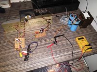
Inpired by this thread I made JLH 1969 version just to see what is that sound everyone here is talking about")
I made one channel while I was waiting for some resistor/caps etc. to start working on Apex fh9 xrk mod and I was just blown away with that litle amp in mono version! So I decided to make second channel and try stereo version on my main technics/bose system.
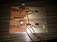
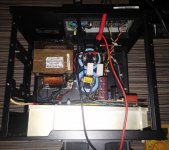
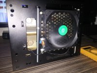
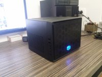
I was thrilled again, sound is awsome, details are a lot better than any of mine previously used amps (ab and d class), bass is strong and tight! I made it entierly of scrap parts I had laying over the room. Outputs are 2 different pairs of old original 2n3055s, bd139 and ei nis 2n2905 transistors. It was so good that I have decided to give it a nice housing and it is my main amplifier now. Higly recommend it to anyone!
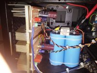
My heatsinks are small and with 1.5A per channell it needs active cooling, but it is not a problem beacuse my comp is next to it so I cant hear that 12cm fan and I can keep my fingers comfortably on heat sinks
Hi to all!
Inpired by this thread I made JLH 1969 version just to see what is that sound everyone here is talking about
I made one channel while I was waiting for some resistor/caps etc. to start working on Apex fh9 xrk mod and I was just blown away with that litle amp in mono version! So I decided to make second channel and try stereo version on my main technics/bose system.
I was thrilled again, sound is awsome, details are a lot better than any of mine previously used amps (ab and d class), bass is strong and tight! I made it entierly of scrap parts I had laying over the room. Outputs are 2 different pairs of old original 2n3055s, bd139 and ei nis 2n2905 transistors. It was so good that I have decided to give it a nice housing and it is my main amplifier now. Higly recommend it to anyone!
My heatsinks are small and with 1.5A per channell it needs active cooling, but it is not a problem beacuse my comp is next to it so I cant hear that 12cm fan and I can keep my fingers comfortably on heat sinks
Attachments

Bigun,
The jlh69 is a fine amp and i use it almost every day.
I think you are right it can by oscillation.
I will try compensation.
Also i ordered a new set 3264 they have also higher gain.
It seem on low volume there is more detail.
Try Hood's compensation a capacitor from collector 2nd transistor to emitter 1st transistor.
330 pF should do the job. Without this lag component your system is analagous to reset an ignition system so it fires dangerously close to to dead centre. There will be no interuption to the feedback at hf which is possible with Miller compensation - an approach deplored by Hood
Hi Weird. Might be an idea to read gannaji's post (#3439) first as JLH's letter there speaks of the need to use all THREE elements of compensation and NOT just one......
Cheers Jonathan
Been there done that 40 years ago. The amplifier was stable without these components if there was separation of the output wiring and the input.
The ClassAB amplifier that followed this used the same voltage amplifier layout, the driver running in Class A leaving the complentary outputs MJ481 and MJ491 as the only switching stage. This circuit is in "The Class A Amplifier Site" hosted by Rod Elliott,
Hood subjected this to listening trials with test subjects against the Class A amplifier.
The audience could not tell them apart. However for builders who preferred Class A operation for intellectual reasons it could be built to run in Class AB or Class A.
The Class AB used 4MHz outputs and the compensation capacitor value was 390 pF. There is a zobel but that is it.
If 2SA and 2SC devices are your choice, you could put them to good use there.
Of course in a non switching stage i.e. there is no switching to slow the ouput stage down - 330 pF should be enough either the Class A or Class AB circuits.
What one is looking for in selecting a capacitor deployed as per Hood is choose you roll off frequency and select a capacitor value equal in impedance to the feedback resistor value.
Hi Wierd that is just the point. JLH said that they are not options....its all or nothing.
refer to the page that is posted #3439.
The cut off frequency of the mod you refer to is around 50 kHz whereas the output transistors are capable of 4MHz.
The stipulation applies to those limitations to deal with a problem of circuit layout. Hood did not incorporate this mod into his own unit. Having tried it myself I can appreciate the reason he didn't.
If 2SC devices are used changes in phase will arise at higher frequency so these are further up the frequency scale and less critical - certainly the phase correction components are not to be seen in other Hood amplifiers using the same voltage gain structure as the Class A amplifier.
I have recently purchased a pair of assembled PNP boards from ebay. Can somebody recommend an optimum transformer? Will I need to adjust quiescent current once fitted? Thanks
Assembeld Hood 1969 PNP MJ2955 Class A power amp board 2 CH amplifier L164-4 | eBay
Assembeld Hood 1969 PNP MJ2955 Class A power amp board 2 CH amplifier L164-4 | eBay
That's difficult to answer quickly.Thanks Weird
What is the benefit of using 2 trafo's? Is it worth the extra cost?
Many of these "simple" power amplifiers have a low PSRR (Power Supply Rejection Ratio)
A large change in the supply rail voltage results in a small change in the output voltage/current.
The bigger this ratio the less the effect at the output.
Using two transformers separates the loading effects of one channel from the output results of the other channel. This can improve performance.
In addition separate secondaries allows complete isolation of the channels. This can benefit performance since it potentially removes hum caused by hum loops.
For most amplifiers these two effects/improvements can be so small that they are almost inaudible.
Unfortunately there is only one way to find out. Buy two transformers and measure the cross channel effects.
Hi all
It is interesting that the JLH10-watt is still discussed some 45 years later. While there is much discussion on the accuracy of simulator tools, at least these may be used to provide greater insight than previously possible. In view of this I attempted to investigate the "three-mod" frequency solution with some surprising results.
First, as originally configured, the bandwidth is around 2MHz and the unity gain is around 10MHz (using BC307B input-BD139 driver and 2N3715 output devices as I had models for these). This implies a faster than 6dB slope with potential instability but the (simple) phase margin appears to be 40 degrees, so at face value it is stable, but not unconditionally.
With the three-mod compensation, it appears each has a detrimental effect. The output RC stage doubles the load, reducing the unity gain frequency point to 5MHz. The 1nF feedback capacitor rolls off the gain at around 60kHz which may limit the perceived "openness" due to composite frequency roll-off (20kHz hearing plus 60kHz amplifier could be only 15kHz net); and finally the RC network across the driver base reduces the gain from about 100kHz upwards, but this would have little impact, I would think, on the audio performance.
On the other hand a simple capacitor compensation or RC network between the driver transistor collector and emitter of the input transistor can improve the phase margin. Without going further into this, a capacitor of around 330pF would limit the frequency response to 200kHz (ten time the audio band) but because this cannot reduce the gain to below 1 the RC network across the base of the driver is still needed. With 100 ohm and 1nF for the driver base network a 330pF and 220 ohm compensation capacitor appears to give a phase margin of 90 degrees.
I would suggest that if capacitive loading were a problem then the better solution would be to use an LR output network and then couple this with the RC shunt network to avoid excessive loading.
Member
Joined 2009
Paid Member
Using two transformers ...
I found in my version that a simple cap-multiplier (or large RC) in the power rail between front-end and output can do wonders for the simulated PSRR of the amplifier.
JLH recommended a cap multiplier in the feed to the whole amp, but I don't think this is necessary at all.
See post #16: http://www.diyaudio.com/forums/solid-state/268846-tgm9-my-version-jlh-69-class-amplifier.html
Power supply importance.
What is a power amplifier? Is it not a power supply modulator?
So in my view, not enough importance is attached to the quality of the power supply and in my experience, the best solution is to avoid at all costs, active devices in it, including capacitance multipliers.
The best results I have had with various diy amps over many years has always been with a generous transformer for each channel, with massive smoothing caps - 50,000uf or more. (I'd use many paralleled smaller caps to reduce the esr these days)
The downside is of course, the cost, but why build a state of the art amp and then skimp on the power supply?
Any active psu circuitry will impact its own signature on the sound, especially at high volume, and this can be compounded by speakers that are a difficult load.
A few years ago I built the high power version of the JLH amp and tried it with a laboratory switch mode psu - it did not sound that impressive.
Capacitance multipliers and regulated psus are tricks of the trade used to cut costs and keep down the size & weight of the amp.
Last edited:
Hi batteryman. Interesting, thank you. Is there a difference here between class-A and class-B? JLH revised the '69 version of the 10watt amp in the following year (1970) with a simplified PSU....i.e. no semiconductors. I think he only noted a slight increase in low frequency distortion. Later he advocated regulated PSU's for his bigger class-B MOSFet power amps and spoke of better bass and channel separation as I recall. Given that the current drawn by the class-A will be much less variable than the average Class-B amp have you experimented with different PSUs on different classes?
Sorry to expect you to have done all the work.....
Merry Christmas and a happy New Year to all the JLH class-A crew.
Cheers, Jonathan
Sorry to expect you to have done all the work.....
Merry Christmas and a happy New Year to all the JLH class-A crew.
Cheers, Jonathan
Member
Joined 2009
Paid Member
Does using the cap multiplier make some difference, or lots of difference, or no difference to the sound output from the amplifier/speaker?
Was any of that difference measurable?
I never tried listening without it (I ended up using a large RC combination instead of a multiplier mind) but it looked so good on paper I had to include it without first prototyping it. It was a blind date.
That's difficult to answer quickly.
Many of these "simple" power amplifiers have a low PSRR (Power Supply Rejection Ratio)
A large change in the supply rail voltage results in a small change in the output voltage/current.
The bigger this ratio the less the effect at the output.
Using two transformers separates the loading effects of one channel from the output results of the other channel. This can improve performance.
In addition separate secondaries allows complete isolation of the channels. This can benefit performance since it potentially removes hum caused by hum loops.
For most amplifiers these two effects/improvements can be so small that they are almost inaudible.
Unfortunately there is only one way to find out. Buy two transformers and measure the cross channel effects.
I see, thanks
I was planning to use an old inkel ma420 as a case. the 2 x heatsinks measure about 170mm long 90 high and 40mm deep each
Will this be enough per channel?
- Home
- Amplifiers
- Solid State
- JLH 10 Watt class A amplifier