Well, the issue is the topology. It uses a phase splitter to drive the output devices. The phase splitter has to work in Class A - because if you let this device turn off then it no longer controls the current flow. And it must control the current flow in at least one of the output transistors even in Class B. In order for the lower output device to turn off (in Class B) you have to let the phase splitter device turn off. At least this is how I see it. So I don't think you can do it - the distortion will be awful.
If you want to have an amp that can operate in Class A and switch out into Class B when it runs out of bias current you need a different topology. A suitable topology would be the more common complimentary output devices so that it's the output devices that do the 'phase splitting' - rather like the JLH Class B amplifier (described on this site: The Class-A Amplifier Site - JLH Class-AB Amplifier)
I think both the simple Class A amp and his simple Class B amp would sound very nice. But do you need the higher power - you may find with the right speakers that the Class A amp is loud enough.
That makes sense.
I was going to go with Class A but thought of trying it running as old tube amps were, biased about 60-70% and then switch to Class A to see if I could hear any difference. Just for curiosity sake. This may take a bit more thought.
I am going to ask something sacrilegious here. I am interested in the earlier 15W capacitive coupled amplifier and was wondering if you could run in Class AB with about 1A running through the outputs at idle. So up to about -3dB of full output it runs Class A. Or am I missing something here?
The original JLH current steering phase splitter was incapable by itself of
shaping drive currents in a non-linear way that would produce AB output
currents. Non-linearity of the default 2n3055 output transistor bends the
wrong way for natural AB with reduced idle current. Indeed idle current
of the JLH output totem is far MORE than the peak output current and in
wasteful excess of linear class A!
If you wish to reduce idle currents in AB fashion, you'll have to sabotage
the ideal constant drive current source that can be steered only two ways.
You'll either need to restrict excess drive current during the AB crossing,
or shunt it somewhere else than output bases during the crossing.
I've found an easy way to shape the drive currents for square law AB
that can be grafted onto an existing JLH circuit. But my AB solution with
Schottkys for current sensing sometimes oscillates. Not recommending
till I figure why it does that. Fine if you just want to use current sense
resistors (instead of Schottkys) to shape for linear class A behavior.
Search the forum for SRJLH, but don't built the AB option unless you
have some deep insight how to fix the oscillations.
Last edited:
I am going to ask something sacrilegious here. I am interested in the earlier 15W capacitive coupled amplifier and was wondering if you could run in Class AB with about 1A running through the outputs at idle. So up to about -3dB of full output it runs Class A. Or am I missing something here?
Is there a reason why? I am hoping that the amp just behaves like any other Class AB amp once it goes into Class B. The power supply will have enough current to supply the demand. Or is the subsequent designs more suited to run this way?
Here is the original JLH running as low as 500ma bias. Lets be clear on the question. Running it at 1 amp as you wish doesn't really fit the accepted definition of Class AB. To me a class AB amp is one running at the correct current for the output stage topology chosen.
Attachments
Here is the original JLH running as low as 500ma bias. Lets be clear on the question. Running it at 1 amp as you wish doesn't really fit the accepted definition of Class AB. To me a class AB amp is one running at the correct current for the output stage topology chosen.
Your making me want to figure out how to use LTspice. Good thing I have a few projects to finish first, looks like I will have to brush up on my transistor theory. I was just trying to get a head start on this one since I have to get the transistors mailed in (Slow boat from China you know).
Your making me want to figure out how to use LTspice. Good thing I have a few projects to finish first, looks like I will have to brush up on my transistor theory. I was just trying to get a head start on this one since I have to get the transistors mailed in (Slow boat from China you know).
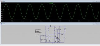
If you install LTspice here is the file that will run straight off. Just unzip the folder and keep the two files together. If you want to try it and get stuck just ask... I knew zilch about using spice 12 months ago.
Attachments
If you install LTspice here is the file that will run straight off. Just unzip the folder and keep the two files together. If you want to try it and get stuck just ask... I knew zilch about using spice 12 months ago.
I had other plans for tonight. Oh well.
")
No.
You have this all wrong.
If the output bias of a single ended SS amplifier is the maximum output current then the maximum power is given by:
Pmax = Ibias^2 * Rload / 2
If the output bias of a push pull SS amplifier allows twice as much maximum output current then the maximum power is given by:
Pmax = [2times Ibias]^2 * Rload / 2
The JLH operates as a sort of sliding bias where the maximum output current of this amp is intermediate between the SE and PP types.
I've seen estimates of 1.5times bias and 1.6times bias. I have not tested so can't confirm actual peak output current.
The maximum power of a JLH is given by:
Pmax = [Xfactor times Ibias]^2 * Rload / 2
If you know that the maximum output current of your JLH is 1.75Apk then the maximum power into 4r0 is 6.125W, not 12.25W
Had you used an 8ohms speaker for your higher voltage JLH and I assume the Xfactor is 1.5 (as before), then the maximum power would be:
Pmax = [1.5*1.75]^2 * 8 / 2 = 27.56W if the output voltage required for this Pmax is within the capabilities of a 46Vdc supply.
Vpp for that prediction is 2 * 1.5*1/75 * 8 = 42Vpp.
This is possibly within the capabilities of your 46Vdc PSU.
There is no advantage in increasing Vdc of the PSU AND reducing the speaker impedance from 8ohms to 4ohms.
Power is power, nothing else.
We are speaking of PowerRMS:
[W RMS] = [A RMS] * [V RMS]
When i misure Ibias with my digital multimeter I measure it by [A RMS] (Ampere RMS), not Apk, nor App of course.
This is because multimeter makes only measurements of Voltage RMS, even if it is measuring Ampere; in fact it then divide Voltage measurement by a shunt resistor, to obtain correct value of I, expressed in [A RMS].
So if I measure Ibias = 1.75A RMS and I connect a 4ohm loudspeaker, then the output power is:
(1.75^2)*4 = 12.25W RMS.
In this calculation I can ignore the voltage value beacause I know it is sure enough. In fact:
1.75A*4ohm = 6.125V
Vcc(min) = 2*(6.125V+0.7V) = 13.65V (<<48V).
So if I want an output power of 12.25W on a load of 4ohm I have to bias my JLH@ 1.75A rms and 13.65V rms.
But it is not so simple.
If I want to drive 2ohm too @12.25W?
sqrt(12.25Wrms/2ohm) = 2.5A rms circa.
{It's different from sqrt(12.25Wrms/4ohm) = 1.75A rms.}
So: 2*(2.5Arms*2ohm+0.7V) = 11.4V rms (but I've got 13.65V, so it's ok). I have to increase Ibias from 1.75A to 2.5A.
8ohm?
1.75Arms*8ohm = 14Vrms.
14Vrms*1.75Arms = 24.5W rms.
So I need a Vcc = 2*(0.7Vrms+14Vrms) = 29.4V rms. (13.65V is no more ok, and I have to increase a lot the PSU).
At the end of the story a correct couple of values to drive whatever @12.25W rms (min) is:
2.5Arms @30Vrms [12.25W rms A Class @2/4 ohm, 24.5W rms A Class @8 ohm].
I agree with you of course when you say 'There is no advantage in increasing Vdc of the PSU AND reducing the speaker impedance from 8ohms to 4ohms'.
I only said I polarized my JLH @48V when someone asked if anybody out there (cit.) did, not said it's a good choice.
Last edited:
FYI:
Irms = Idc
Vrms = Vdc
RMS values don't apply to DC, only to changing quantities.
If the Ibias of the JLH69 is reduced to around 500ma (which is a static DC value) then the output can still swing almost 5 volts RMS into 8 ohms when running on a 17 volt supply. The actual peak current in the output stage will be around 900ma (falling almost to zero as the output voltage swings to ground) and with an average around 0.47A and RMS value around 0.56A
The current in the load (which is ground referenced and AC coupled) will be in the region of -/+0.9 amps peak and an RMS value of around 0.6 amp. There is no "average" current flowing in the 8 ohm load for a sinewave because its ground referenced, or more correctly the average is zero for a sinewave.
RMS values don't apply to DC, only to changing quantities.
I only said that RMS value, say 500mA, of a sinewave current is equipollent to 500mA DC current. This is (one) definition of RMS value.
If the Ibias of the JLH69 is reduced to around 500ma (which is a static DC value) then the output can still swing almost 5 volts RMS into 8 ohms when running on a 17 volt supply.
500mA of Ibias = 500mA pk or = 500mA RMS ?
I think we are saying same things; I said that multimeters can make only RMS measurement, so when I read an Ibias = 1.75A it means an Ibias = 1.75A RMS.
Ok, RMS doesn't make sense about DC stuff, but it's a way to say that DC it's equipollent to RMS, not to peak value.
In fact max pp value of the output current signal will be = 1.75A*sqrt(2)*2.
If the reading on the display of DC current value on my digital multimeter would be equipollent to Ipk, we should have an output current signal (pp value) = 1.75A*2, or an Ibias = 1.75A / sqrt(2).
And this fact makes difference when I have to calculate the bias or say how many watts my ampli is able to express.
I think this stuff it's a little more complicated than it seems to be - and I don't understand why - but I say this beacause it seems that every person or website out there have proper definitions and workflows to calculate Ibias and Vcc.
And this appens only about audio stuff
More often than it should be, audiophiles speake about these arguments without any proper acquaintance, and this explanes - IMHO - why always there are misunderstandings about these things.
Actually I'm speaking in general, not about this specific 3D (or - better - forum).
So, when you say 500mA I think (better, I hope to understand what you want to say) you mean 500mA rms (equipollent to my 1.75A rms
)17VdcBias means Vpk = (17/2) - 0.7 = 7.8Vpk circa, or 7.8/sqrt(2) = 5,15Vrms = circa 5Vrms.
This value would be the same even if the loud would be 4ohm and it is incorrelate, until a specific value, to Ibias; it is directly tied to Vcc.
So: 7.8Vpk / 8ohm = 975mA pk.The actual peak current in the output stage will be around 900ma
Yes, but whit an Ibias = 500mA we can only have an Ipk = 500mA*sqrt(2) = 700mA circa.
In this case we have 275mA of undervalue, that it means that after 700mA pk output current the amplifier is (heavily) clipping.
Ok: you are speaking of output current on the load.(falling almost to zero as the output voltage swings to ground)
If we are speaking of sinusoidal current it doesn't make sense to say average, in fact the average is actually zero, so I don't understand what do you want to say....and with an average around 0.47A and RMS value around 0.56A.
I don't understand what do you want to say with RMS value: why 0.56A?
If Ibias = 500mA DC current it means RMS output current = 500mA. No doubt at all on this point.
The current in the load (which is ground referenced and AC coupled) will be in the region of -/+0.9 amps peak and an RMS value of around 0.6 amp.
Again, I agree with +/-0.9A (but whit the limitation of clipping), but I don't understand what do you mean with RMS value.
(EDIT: ok, you mean RMS value of +/- 0.9A. But you have to consider that is impossible to correctly drive a load of 8ohm with a supply of 17Vdc at full power without clipping if Ibias is set to 500mA; amplifier needs an Ibias around 0.6A, that is the value that you call RMS).
There is no "average" current flowing in the 8 ohm load for a sinewave because its ground referenced, or more correctly the average is zero for a sinewave.
In fact.
Last edited:
Well we are talking about a very specific circuit here and you have to take the bootstrap part of the circuit into account as well because that alters the dynamics of it all completely. Remove the bootstrap (which changes nothing DC wise) and you lose a lot of "positive" drive capability.
Ibias is the steady state quiescent current that you set to flow in the output stage. For this circuit (in its standard form) the output can deliver approximately Ibias * 2 for positive excursions in output. Negative excursions (the bottom half of the sinewave if you will) have no such restriction. So that does give asymmetric clipping, but for an 8 ohm loading it will deliver just short of 5 volts RMS.
Hello,
I just finish my JLH HOOD 1969 10W with 2sc5200
but the result is not very fine,
I have a power supply 16 to 28V,
normally this item works with +27V, but if I use +27V, the sound is very horrible with pic..
I find a good voltage, +16V, but for me it's not normal voltage..
anybody can help me ?
thanks
Just wanted to share my JLH progress with other JLHers. I am using the 2SC3280 transistors and I'm not super sure what power supply wattage to shoot for. I supposedly have a 200W SMPS on the way from Connexelectronic but I fear that may be too large to power the stereo pair.
And the preamp that I built to feed the JLH
An externally hosted image should be here but it was not working when we last tested it.
An externally hosted image should be here but it was not working when we last tested it.
And the preamp that I built to feed the JLH
An externally hosted image should be here but it was not working when we last tested it.
The amp will draw whatever it is constructed to draw. You can't have to large a capacity supply.
If the amp pulls 2 ? amps at 27 volts then you need at least a 54 watt supply. Double that for two channel. Add a safety margin too. say 140 watt supply needed for that example for two channels.
Is the 200 watt SMPS rated 200 watts output or is that what its nominal power consumption from the mains is. There's a big difference. 200 watts mains consumption will be nothing like what it can deliver to a load.
The amp will draw whatever it is constructed to draw. You can't have to large a capacity supply.
If the amp pulls 2 ? amps at 27 volts then you need at least a 54 watt supply. Double that for two channel. Add a safety margin too. say 140 watt supply needed for that example for two channels.
Is the 200 watt SMPS rated 200 watts output or is that what its nominal power consumption from the mains is. There's a big difference. 200 watts mains consumption will be nothing like what it can deliver to a load.
SMPS is rated for 200W of output. Good to know the amp will not draw more than it is constructed to. Since it uses the SiliconRay 10W kit (2N3055 swapped for 2SC3280 for convenience of wall mounting, datasheets paint them as nearly identical). SO with an Iq of ~2A and a rail voltage of 22V I could get away with a 120W PSU (2*22*2 = 88W)? 88W in for 20W out (total) is what, 22% efficiency?
The real problem is where to find a very compact center-tapped PSU. I placed that order with Connexelectronic on April 8 and have heard literally nothing from them. I could have ordered twice from overseas in this time frame.
The heatsinks will be too small for this much (54W per channel) power dissipation.
Oh lawd yes. 54W of heat load is like a desktop processor.
Last edited:
I supposedly have a 200W SMPS on the way from Connexelectronic but I fear that may be too large to power the stereo pair.
If I was using a SMPS (switch mode power supply) I'd not be mounting it in the same chassis as the amplifer. And I'd be putting a pile of noise reduction (staged sets of pi filters) between the amp and the SMPS. Given this is Class-A you can get very serious about it: F3db for the PS is below 1hz.
But remember that there is a reason Jean Hiraga used batteries.
If you install LTspice here is the file that will run straight off. Just unzip the folder and keep the two files together.
Hey thanks for that, what a cracking new toy.
What do you make of the signal current in the V1 (17v) supply though – should that be there d'you think?
- Home
- Amplifiers
- Solid State
- JLH 10 Watt class A amplifier