Uncharted territory but you could halve the value R6 and double the value of C4. That would double the gain. But... you are changing the whole design of the amp... that said it isn't a JLH69 in the true sense anyway.
Why do you feel changing the gain of the amp is preferable to adding gain to the preamp ?
Why do you feel changing the gain of the amp is preferable to adding gain to the preamp ?
So that is why I'm looking for some gain, but I don't like to ditch the nice sounding B1 or add gain stages to it. Some more gain in the power amp would be great.
You think you need gain
 . If you don't want to ditch the B1, well, regardless the shunt power supply, DCB1 will most probably solve your problem.
You think you need gain
OK, I'll admit: I have a DCB1. Why would that solve my problem?
The gain is set by the feedback factor of R6 and R8 in the circuit in your link (the transistors have no influence). Altering the gain could/would alter the whole character of the amp, its stability margins and DC conditions.
Thank you, somehow I missed your reply earlier.
Could you please elaborate a bit? Are there any guidelines for this, how much gain can be achieved, does anyone have experience in doing this?
I assume it is not as easy as inserting a trimpot in the position of R6 and or R8 and adjusting ..
Thanks, MArco
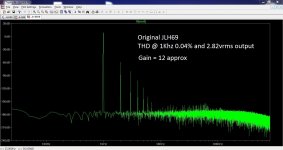
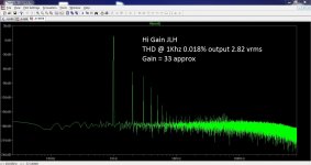
It just happens I have the original JLH69 as a simulation and so changing the 220 ohm to 82 ohm was easy to try. That changes the gain from 12 to 33. The raw numbers suggest the THD is lower for the higher gain version. You would have to increase the value of the cap in proportion.
Attachments
Has anyone played around with the 1969 JLH running at higher rail V, say 46V?
Yes, I did.
48V@1,7A.
For 4ohm load.
With 2sc5200.
If the JLH biasing allows 50% more output current than the quiescent bias, then your maximum output is 13W into 4r0.Yes, I did.
48V@1,7A.
For 4ohm load.
.......
What was the point in raising the supply voltage and then hanging a 4ohms speaker on the output?
ok so I have been trying to get my jlh circuit to work with a Connexelectronic smps and I am having a problem. With everything wired up and nothing connected to the inputs on the board, the amp is silent. If I connect a wire to the inputs I get oscilation. If I connect the input to the chasis RCA I get ground noise. I have played around with a few different configurations but I am starting to run out of ideas.
FYI circuit is JLH 69. SMPS is at 46V - High but I have big heat sinks.
Any ideas?
* I just built a voltage dropping circuit using some spare resistors on hand to see if it helped. It seems like it improved things but I am still getting some noise on the outputs. I know that the original circuit design had a table to change the resistors values of R1 and R2 depending on the output load and the minimum PS voltage and input V. Considering I have a higher V PS and modern sources have 2V of output should I consider changing them or is this unrelated to my problem?
http://www.angelfire.com/sd/paulkemble/jlhclapaorig.gif
Last edited:
If the JLH biasing allows 50% more output current than the quiescent bias, then your maximum output is 13W into 4r0.
What was the point in raising the supply voltage and then hanging a 4ohms speaker on the output?
I only build one version, the early '69 one. Without biasing the output current. I played with the two resistors whit trial and error methode, and i stopped when i found about 48V@1.75A, to allow enough power @4ohm.
I don't remember now which value i choose, i'm sorry.
And at the time i was without the scope. I only remember - and i'm sure - it was a very high performing amplifier, very hot and with very large heat sink.
I remember too the voltage dropped in the first 15/20 minutes from 49v to 47.5v, because of the thermal derating, and then it was rock solid, for what i could see without the scope - pure resisting load of 4ohm/20W and monitoring the voltage with multimeter.
So i think there was no oscillations.
I know maximum output power is about 13W into 4ohm: actually
@48V i got 1.75A X 24V = 42W maximum output power (dissipation); with a load of 4ohm i got 1.75^2A X 4ohm = 12.25W maximum output power.
So of course 1.75A @48V @4ohm is an experience to try and stop.
No........................I know maximum output power is about 13W into 4ohm: actually
@48V i got 1.75A X 24V = 42W maximum output power (dissipation); with a load of 4ohm i got 1.75^2A X 4ohm = 12.25W maximum output power.
.........................
You have this all wrong.
If the output bias of a single ended SS amplifier is the maximum output current then the maximum power is given by:
Pmax = Ibias^2 * Rload / 2
If the output bias of a push pull SS amplifier allows twice as much maximum output current then the maximum power is given by:
Pmax = [2times Ibias]^2 * Rload / 2
The JLH operates as a sort of sliding bias where the maximum output current of this amp is intermediate between the SE and PP types.
I've seen estimates of 1.5times bias and 1.6times bias. I have not tested so can't confirm actual peak output current.
The maximum power of a JLH is given by:
Pmax = [Xfactor times Ibias]^2 * Rload / 2
If you know that the maximum output current of your JLH is 1.75Apk then the maximum power into 4r0 is 6.125W, not 12.25W
Had you used an 8ohms speaker for your higher voltage JLH and I assume the Xfactor is 1.5 (as before), then the maximum power would be:
Pmax = [1.5*1.75]^2 * 8 / 2 = 27.56W if the output voltage required for this Pmax is within the capabilities of a 46Vdc supply.
Vpp for that prediction is 2 * 1.5*1/75 * 8 = 42Vpp.
This is possibly within the capabilities of your 46Vdc PSU.
There is no advantage in increasing Vdc of the PSU AND reducing the speaker impedance from 8ohms to 4ohms.
Member
Joined 2009
Paid Member
* I just built a voltage dropping circuit using some spare resistors on hand to see if it helped.
From a power dissipation point of view this makes no difference, it just shifts a bit of the power dissipation from the devices on the heatsink to the spare resistors. I'd rather have the extra voltage across the power devices for better linearity and also not have the resistors increasing power supply impedance (unless you put big caps after them).
Bias current is also not just about max power but it affects the operating point of the devices - it affects linearity.
I am going to ask something sacrilegious here. I am interested in the earlier 15W capacitive coupled amplifier and was wondering if you could run in Class AB with about 1A running through the outputs at idle. So up to about -3dB of full output it runs Class A. Or am I missing something here?
I am going to ask something sacrilegious here. I am interested in the earlier 15W capacitive coupled amplifier and was wondering if you could run in Class AB with about 1A running through the outputs at idle. So up to about -3dB of full output it runs Class A. Or am I missing something here?
That should work.
You can drop the current down substantially. The limiting factor in the original design for doing this is the lack of base current for the top output transistor, or rather the lack of hfe for the limited base current. Altering it for one amp (1A) is no problem though.
Member
Joined 2009
Paid Member
I don't think the original JLH can run in AB, it falls apart badly when it runs out of current.
Is there a reason why? I am hoping that the amp just behaves like any other Class AB amp once it goes into Class B. The power supply will have enough current to supply the demand. Or is the subsequent designs more suited to run this way?
Member
Joined 2009
Paid Member
Well, the issue is the topology. It uses a phase splitter to drive the output devices. The phase splitter has to work in Class A - because if you let this device turn off then it no longer controls the current flow. And it must control the current flow in at least one of the output transistors even in Class B. In order for the lower output device to turn off (in Class B) you have to let the phase splitter device turn off. At least this is how I see it. So I don't think you can do it - the distortion will be awful.
If you want to have an amp that can operate in Class A and switch out into Class B when it runs out of bias current you need a different topology. A suitable topology would be the more common complimentary output devices so that it's the output devices that do the 'phase splitting' - rather like the JLH Class B amplifier (described on this site: http://sound.au.com/tcaas/jlhab.htm)
I think both the simple Class A amp and his simple Class B amp would sound very nice. But do you need the higher power - you may find with the right speakers that the Class A amp is loud enough.
Last edited:
- Home
- Amplifiers
- Solid State
- JLH 10 Watt class A amplifier