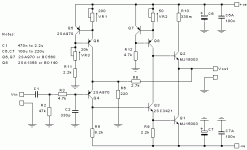
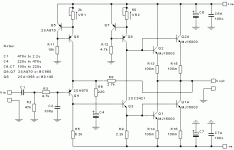
you will probably have to go back and forth between them. As you adjust one the amp temperature will change. That will require a further adjustment. 25T pots in parallel with fixed resistors can make fine adjustments much easier once you know roughly what resistances you need.
I received this from Geoff Moss when I used his PCB design to build my JLH. You'll have to check whether his VR1 & VR2 match the schematic you're using. The instructions are based on the schematic of Fig. 3 at http://www.tcaas.btinternet.co.uk/jlhupdate.htm:
As for initial setting-up, before power is first applied I would adjust both VR1 and VR2 for maximum resistance. After power is applied, VR1 is adjusted to set the output dc offset to near zero and the quiescent current (and current sharing) checked by measuring the voltages across the 0R1 resistors. If all seems well, VR2 is adjusted to raise the quiescent current to, say, 1A. After a short period to allow the transistors to warm up, the output dc offset is reset to near zero by adjusting VR1. Back to VR2 again and raise the quiescent current to, say, 2A. Wait a while and reset the output offset.
Unfortunately, the adjustments of VR1 and VR2 interact and so the setting of the quiescent current and output dc offset is an iterative process but after about four steps you should be able to get the current and offset somewhere near to the required values. At this point, it is necessary to let the amp idle for an hour or so in order to ensure that thermal equilibrium has been reached and that the amp is at its normal operating temperature. The quiescent current and output dc offset are now trimmed to the required values. These are best rechecked after a further settling period (say about 30 minutes).
after about four steps you should be able to get the current and offset somewhere near to the required values[/I]
Required values?
Is VR3 redundant?
Required values?
DC Offset as close to 0 as you can get. What's acceptable is your decision.
Current is also your decision. Current and voltage together determine the heat dissipation in your output transistors. Your heat sink must be able to cope with that (and of course the transistors must be able to cope to).
DC Offset as close to 0 as you can get. What's acceptable is your decision.
Current is also your decision. Current and voltage together determine the heat dissipation in your output transistors. Your heat sink must be able to cope with that (and of course the transistors must be able to cope to).
Required values?
DC Offset as close to 0 as you can get. What's acceptable is your decision.
Current is also your decision. Current and voltage together determine the heat dissipation in your output transistors. Your heat sink must be able to cope with that (and of course the transistors must be able to cope to).
Thanks.
Hi, the BT's free web hosting service is now closed is down, does anybody has a backup of the pdf(s)?
Some are still cached by google, but most (all) site is avail in web archive:
The Class-A Amplifier Site
I suggest to save all pages as pdfs.
The Class-A Amplifier Site
I suggest to save all pages as pdfs.
Hi, the BT's free web hosting service is now closed is down, does anybody has a backup of the pdf(s)?
Darn! I should save the docs as PDFs instead of just the link. Now it is too late. Jonathan is right, the archive does not have the most recent update. Can anyone help, please!
Regards,
What exactly are you looking for? I have some gif's from the version I built, attached.
Sadly, I think this means Geoff is no longer able to maintain his site. He was very helpful to me while I was building my amp.
Sadly, I think this means Geoff is no longer able to maintain his site. He was very helpful to me while I was building my amp.
Attachments
Last edited:
What exactly are you looking for? I have some gif's from the version I built, attached.
Sadly, I think this means Geoff is no longer able to maintain his site. He was very helpful to me while I was building my amp.
Hi, Paulb,
Thank you for the post. Yeah, too bad. I think Geoff is finally decided to "close the shop". He is a nice guy - replied to my queries patiently and cordially. Actually, he referred me to your "blog" for some informations that are absent in the TCAA site. My high power JLH class A is far from finished
I guess I am missing the more recent updates/edits. The last piece of info that I have was updated on 2005. I did not realised that are further update in 2009, as mentioned by Jonathan.
Regards,
You can post your questions here, I'm subscribed and will try to answer but others will be helpful as well.
Well,
I would be quite happy to host Geoff's site rather than see it go offline.
Geoff Moss & TCAAS
Hi there all,
I recently corresponded with Geoff, and yes he has gone through a spell of bad health. I was looking for suggestions for the ESL Class-A and he very kindly replied. I agree with Bonsai, lets try and keep TCAAS up and running. I am also happy to host a mirror site here in SA. I'll just have to find out how to go about it. I'll see if BTInternet will speak to me.
Kevin
Last edited:
You can post your questions here, I'm subscribed and will try to answer but others will be helpful as well.
Right! The guys here are always helpful.
Regards,
Hi there all,
I recently corresponded with Geoff, and yes he has gone through a spell of bad health. I was looking for suggestions for the ESL Class-A and he very kindly replied. I agree with Bonsai, lets try and keep TCAAS up and running. I am also happy to host a mirror site here in SA. I'll just have to find out how to go about it. I'll see if BTInternet will speak to me.
Kevin
To Bonsai and Ferret,
That will be great. Those are worthy informations to "keep alive". Thanks guys!
Regards,
- Home
- Amplifiers
- Solid State
- JLH 10 Watt class A amplifier

