Member
Joined 2009
Paid Member
Hi all, Bigun, the cap multiplier I used was one from the class A website. There was no extra capacitance fitted after it, large value caps were used before it as per the diagram.
I suspect that it's important to have large capacitance after the multiplier. The cap multiplier has a relatively high output impedance and you don't want any of the signal current flowing through the active device or it will add it's exponential characteristic to the signal distortion even if at a very low level. With large caps after the multiplier you have a chance to isolate the amplifier signal current from the multiplier. This is just my theory on the matter but perhaps it means that the cap multiplier is still in the game... as I see a variation on the multiplier being useful in controlling bias current runaway.
I assume this means that 2nd order is no problem for you, but I also assume you'd like to reduce anything higher in order.I'm not looking for significantly lower distortion from the JLH 1969
For what it's worth, I'm OK with nfb as long as it isn't being used as a method of reducing problem distortion.I don't consider more nfb a step in the right direction although I know some people do and that's OK with me too.
So I can see your point about the CCS's as a trade off between increased higher order distortion and reduced 2nd order...versus lower overall distortion. I wouldn't go there either in this case.
No argument, but for what it's worth, it doesn't sound bad with all such capacitance removed.I suspect that it's important to have large capacitance after the multiplier.
Member
Joined 2009
Paid Member
Yes indeed, I don't have a problem with 2nd order although too much can be bad for IM on complex music. And yes again, higher orders, especially 5th and above are to be despised from all that I've read. But I already have to live with some consequences of starting out with the 2N3055's for now...
I've worked out, I think, how to glue the bits of heatsink together to give me something useable. Maybe not great or elegant but all in the spirit of DIY ! If I can find time to actually assemble these metal pieces I'll post a photo or two.
I've worked out, I think, how to glue the bits of heatsink together to give me something useable. Maybe not great or elegant but all in the spirit of DIY ! If I can find time to actually assemble these metal pieces I'll post a photo or two.
wrong conclusion.
A ClassA amplifier, whether a Power amplifier or Pre-amplifier or a single stage single ended amplifier is only constant current when there is Zero output current, i.e. in the quiescent state.
Hi Andrew,
Surely this depends on the design - if the o/p stage has a CCS as a "load resistor" then the current, to all intents & purposes, is constant.
Of course this current is shared between the load & the o/p devise - so in as much as there is a signal it is not constant in the o/p devise - but to the PSU it should be more or less constant.
This would be even more so in a balanced working design where even tiny variations will be equal & opposite and will cancel each other.
mike
Last edited:
Hi all,
BIGUN, I am confused regarding using high value caps after the capacitance multiplier or indeed other types of series regulators. Rod Elliot has designed a cap multiplier for the JLH ( ESP project 15 )and he quite clearly recomends not using a large value cap after the series transistor due obviously to the charging current for that cap that would have to flow through the transistor.
Have I missed something?
Can I have your views ( or anyone else ) about this please, I am very willing to learn.
Alan
Isnt the 'only' 1000uF capacitor in ESP proj 15
because it does not make sense to have a big capacitor
when already we have an output of multiply capacitance
in the transistor.
The charging of the 1000uF will be a fairly slow process
because the caps at the base of transistor will graduly charge.
because it does not make sense to have a big capacitor
when already we have an output of multiply capacitance
in the transistor.
The charging of the 1000uF will be a fairly slow process
because the caps at the base of transistor will graduly charge.
Member
Joined 2009
Paid Member
I can't comment regarding Rod Elliot's thoughts, he's far more experienced than I but I will try to describe my thoughts.
There are two separate tasks to be performed by the supply rail capacitors, a) low pass filter for the ripple from the rectifiers, b) low impedance return path for signal current flowing through the load.
For a) the objective is simply to create a smooth dc supply. The Cap Multipliers main purpose is to simulate a very large capacitance which has the function to reduce ripple and noise on the supply. I believe it's a very bad choice of circuit to create a low impedance path for signal current returning from the load because it's a non-linear element and has a relatively high impedance. I don't really see a problem in having a large capacitor after it - so what if this large capacitor must be charged through the cap multiplier ? the power supply including cap multiplier will supply several amps of current, quite sufficient to charge up some capacitors.
For b) I want high quality capacitors. I'd prefer not to have power supply ripple filtered by the same capacitors as those in the return path for the load current because then I have intermodulation between the signal current and the power supply ripple. I don't know exactly why that would be bad, but it sounds as if it would be. I also believe with suitable design that it's possible to improve channel-channel separation too.
Alibear - there are 'other series regulators' that might well complain about having capacitance after them. I'm not familiar with these issues as I've never used them. These 'other' regulators I refer to are feedback regulators, often an i.c. - they are amplifiers in their own right and their stability can be adversely affected by the load they are driving into. I don't see that as an issue which affects a capacitance multiplier - it has no loop feedback.
Last edited:
This statement is almost true, if you take out "even tiny".This would be ...so in a balanced working design where even tiny variations will be equal & opposite and will cancel each other
All the rest of your post is untrue.
Member
Joined 2009
Paid Member
All the rest of your post is untrue.
That's a bit harsh maybe ? Perhaps there is a misunderstanding of what is being said. I interpreted Mike's comments as related to an example of a Single Ended output stage, with a CCS load. On this basis, I thought his comments were spot on.
I understand that there has been some debate as to whether the JLH is a push-pull or a kind of modulated single ended output. My view on the project I'm building is that this is a push-push output so the case of a simple CCS load doesn't apply.
Last edited:
Member
Joined 2009
Paid Member
If the supply rails are 'perfectly' decoupled with rail capacitors this modulated current in the supply rails flows only between the output stage and the rail capacitors. Beyond the rail capacitors (i.e. between rail capacitors and a d.c. power source) the supply rails would experience a constant current draw.
The issue of course is the lack of perfect decoupling. But we can get close by using large and good quality capacitors.
We also want to have a good d.c. power source, meaning that the ripple from an a.c. power source is taken care of before the power reaches the output stage decoupling capacitors.
The issue of course is the lack of perfect decoupling. But we can get close by using large and good quality capacitors.
We also want to have a good d.c. power source, meaning that the ripple from an a.c. power source is taken care of before the power reaches the output stage decoupling capacitors.
Last edited:
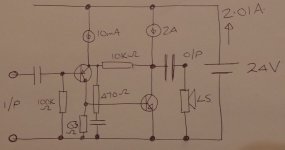
Well, that depends a bit on the exact topology used. I am not commenting about any specific design - just general principals. you seem to be saying that a signal will always change the load on the PSU and this simply is not true.
If you imagine a single ended amp with the gain stage on the output. o/p stage load resistor = CCS. Single rail, with i/p & o/p caps lets say CCS set to 2A. 8ohm load and assuming the CCS works reasonable well.
In steady state: CCS = 2A. o/p transistor = 2A. load = 0A
with 8V peak o/p signal: CCS = 2A. o/p transtisor = 1A. load = 1A
with -8V peak o/p signal CCS = 2A o/p transistor = 3A. load = -1A
So the only change of current is in the o/p transistor & the load. These are then joined together and grounded and once the currents are combined like this a constant 2A will flow back to the PSU.
do you see ?
mike
Last edited:
")
Member
Joined 2009
Paid Member
Yes, this is a very neat topology and offers built-in dc speaker protection. And if I understand you correctly, I agree with your assertion over constant current. But, this output cap approach only isolates the power supply from the load currents when it's implemented in a single ended design which the JLH in my view, is not.
Also, this topology does introduce that fear of distortion from a capacitor in series with the load that seems to get some audiophiles to come out in hives and a cold sweat. I'm not in that camp, but I see that the output capacitor distortion is not reduced by the effects of nfb. The dual rail approach solves that problem because the relevant capacitors are now rail decoupling capacitors and the nfb loop controls the distortion at the load with the rail capacitors out of the way.
Also, this topology does introduce that fear of distortion from a capacitor in series with the load that seems to get some audiophiles to come out in hives and a cold sweat. I'm not in that camp, but I see that the output capacitor distortion is not reduced by the effects of nfb. The dual rail approach solves that problem because the relevant capacitors are now rail decoupling capacitors and the nfb loop controls the distortion at the load with the rail capacitors out of the way.
Last edited:
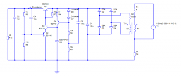
How about this for a simple PSU?
Ripple voltage (30V/3A) 10 mV p-p compared with 2V p-p on main capacitor. Pass transistor needs to be able to dissipate ~ 50W worst case. Transformer nominal rating 34V/4.5A. Assumed winding resistances used to calculate ripple etc. However, due to diode action RMS primary current is ~980 mA instead of normally expected .5A, so probably 5-6A transformer needed to keep dissipation reasonable.
Generic 6A diodes shown can be replaced with a bridge rectifier.
Voltage measurement resistor chain can be split with lower resistor set to 100 ohms and a 47 or 50 ohm pot between the top and bottom resistors with the base of PNP to wiper.
John
Member
Joined 2009
Paid Member
Yes, this is a very neat topology and offers built-in dc speaker protection. And if I understand you correctly, I agree with your assertion over constant current. But, this output cap approach only isolates the power supply from the load currents when it's implemented in a single ended design which the JLH in my view, is not.
Also, this topology does introduce that fear of distortion from a capacitor in series with the load that seems to get some audiophiles to come out in hives and a cold sweat. I'm not in that camp, but I see that the output capacitor distortion is not reduced by the effects of nfb. The dual rail approach solves that problem because the relevant capacitors are now rail decoupling capacitors and the nfb loop controls the distortion at the load with the rail capacitors out of the way.
Hi Bigun,
I was not recommending that you or anyone should build the design I posted - if anyone wanted to use that exact topology it would have to be refined, optimized etc. Rather, I was just trying to demonstrate that this topology, due to the o/p signal current flow paths, does have an simple elegance which is lost with dual rail design and I think it was a dual rail design that Andrew was referring to.
If very simple current flow paths and constant PSU current draw were considered important then I would use the design I posted and go balanced with an earth arrangement as discussed before thus keeping all of the advantages and eliminating most of the disadvantages - cap coupling etc.
I wonder how you project is progressing
cheers
mike
p.s. oh, and the PSU is isolated from the current swings even with JLH design in balanced ( but I understand this does not work in your current system )
Last edited:
mikelmHi Bigun,
I was not recommending that you or anyone should build the design I posted - if anyone wanted to use that exact topology it would have to be refined, optimized etc. Rather, I was just trying to demonstrate that this topology, due to the o/p signal current flow paths, does have an simple elegance which is lost with dual rail design and I think it was a dual rail design that Andrew was referring to.
I have certainly explored that topology before.
It is as simple it gets and still have low distortion.
The drawback is the somewhat low Class A efficiency.
- Home
- Amplifiers
- Solid State
- JLH 10 Watt class A amplifier