Yes, 5 sinks if you have a regulated supply as well. That type of heatsink assembly with 5 sinks on long bolts or long threaded rods in series, would be something to behold but rather prone to damage. Top marks to anyone who succeeds in building it and it remains in regular use for a year or more 
Last edited:
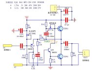
I see the heasink ideally forming the back of the case also the use of plastic power transistors, I've attached a later JLW class amp version which might be of interest. I think this is the last one published. Other PS arrangements could still be used but split supply.
Attachments
'Not easy to shape a large finned heatsink such that it has flat, smooth areas for the power socket, signal and speaker connectors. I do like the idea of just bolting plastic output devices to the smooth inside surface but milling the connector socket mounting surfaces down from the finned side, would likely require some serious machinery.
I'd have the heatsink fins and a pilot light (LED etc.) to the front and switch the power, make connections etc on the rear to keep it simple and easy. If you really need the power switch up front, a push-push action power switch could be mounted inside and coupled to the front panel with a suitable length of extension rod, 6mm diameter, rigid type plastic.
I'd have the heatsink fins and a pilot light (LED etc.) to the front and switch the power, make connections etc on the rear to keep it simple and easy. If you really need the power switch up front, a push-push action power switch could be mounted inside and coupled to the front panel with a suitable length of extension rod, 6mm diameter, rigid type plastic.
Last edited:
Lets correct that above.....I mean for the rod to pass easily through the front panel via a bush or sleeve and then cap it with a suitable 6mm hole button or other reliable arrangement, and to one side of the heatsink, such that your finger will be clear of it 
Last edited:
One heatsink with a flat mounting surface with plastic transistors would be a simpler option, I agree. Especially if the conventional stack of 4 or 5 sinks has uninsulated transistors. Probably a big chance of a short before a mechanical malfunction. So the question then is
- is this stereo, and what size is the box which would set the size of the heatsink? Then you would need to look for deep fins I suspect. With max. 2.2C/W per transistor uninsulated the total thermal resistance for a typical power transistor (1.5C/W) is 3.7C/W. Dissipating 17W each gives a 37C rise on the heatsink but 63C rise on the junction - quite hot but manageable. Four devices means a heatsink of 0.5C/W or less if you also include a PSU transistor. The transistors will need insulators but a modern high power device may have 1C/W so back to 1.5 with insulator.
Question - is there a 0.5C/W heatsink which neatly fits the OP's box?
Over to you, OP.
Ian - the orignal photo showed mains input etc on the new front panel, no need for that on the heatsink. Though I'd prefer mains input at the back, it seems heatsinking is the question to be resolved here.
Mine would be more like JLH's connection and switch on the front which could be turned round but people would be looking at a heatsinkNot easy to shape a large finned heatsink such that it has flat, smooth areas for the power socket, signal and speaker connectors.
There are options though such as extending the heatsink with a piece of aluminium. or 2 one for power and out and the other for input at each end. Make them thick enough or bend and as with the heatsink they can form part of a case support top sides and bottom using suitable sizes of aluminium sheet. Front in my case probably plastic several mms thick. Simple fixings. self tappers or what ever.
Power dissipation in a regulator. It looks to me like he mounted the power device for that on the case holding the actual amp. Inside as well. The smoother probably dissipates less than a true regulator as in theory it's just handling ripple which due to cap sizes wont be a lot. On a regulator power that is disipated depends on lost voltage and ripple content. In both cases it wont be a lot.
") There was always a bit of competition in WW so attached another design. To my mind JLH wins hands down. I well remember buying my last copy. The lady behind the counter stepped back as I approached; A company took it over and there was very dramatic change. Some customers got very annoyed. Lots were annoyed even me. It's replacement has never ,matched up. Loss of an excellent educational resource also the designs.
There was always a bit of competition in WW so attached another design. To my mind JLH wins hands down. I well remember buying my last copy. The lady behind the counter stepped back as I approached; A company took it over and there was very dramatic change. Some customers got very annoyed. Lots were annoyed even me. It's replacement has never ,matched up. Loss of an excellent educational resource also the designs.Attachments
Last edited:
The Sugden DIY design article was another great read - I don't think I've seen it before or perhaps just forgotten. Thanks for posting it.
As far as E&WW magazine is concerned, I believe many professionals organisations who subscribed to it, consistently objected to an increasing number of amateur level, subjective views and erroneous claims that were solely about audio but were still accepted and published.
At least they were often entertaining articles - more so than the re-published extracts of books, textbooks, app notes and other past articles that followed until the magazine folded in 2008. Perhaps they just didn't have the cash to remunerate the authors of contemporary material and ran out of material or relevance. Hasn't web publishing largely displaced books, magazines and printed printed material in general, from pro. resource materials?
In October 1983 the magazine became "Electronics & Wireless World"
That was due to changes in the electronics area wireless was too narrow a word. The final buy out. Pass, There could be a number of reasons including a decline in DIY building,
Erroneous claims. Getting something published was an achievement and also surviving the readership's scrutiny, I suspect there was a fairly closed circle of designers or in some cases find some one who could do it, I phoned them once asking about an early oscilloscope design. They said it wasn't adequate any more and were thinking about doing another. Shortly after it appeared and i had great fun with a high voltage self oscillating to sine wave inverter.
Off topic again so no more.
That was due to changes in the electronics area wireless was too narrow a word. The final buy out. Pass, There could be a number of reasons including a decline in DIY building,
Erroneous claims. Getting something published was an achievement and also surviving the readership's scrutiny, I suspect there was a fairly closed circle of designers or in some cases find some one who could do it, I phoned them once asking about an early oscilloscope design. They said it wasn't adequate any more and were thinking about doing another. Shortly after it appeared and i had great fun with a high voltage self oscillating to sine wave inverter.Off topic again so no more.
Back to my heatsink suggestion for the front panel - Quad seemed to like the idea of front panel 'sinks but large heatsinks aren't something stocked by many distributors. We have a local maufacturer here in Oz, who casts and finishes a wide range of custom heatsink products, sells direct and the quality is excellent, considering the necessary techniques. Fine for me, but I'm sure UK and other global members would prefer your own local source though I've not seen many in advertising.
Most heatsinks sold by distributors are small, extruded forms with low thermal capacity or occasionally, chunky custom shapes that look like props for a Sci-Fi movie. Here's what I think will suit, from the Conrad heatsinks range. It's type MF20, Height 75mm with a thermal resistance of 0.55 K/Watt, which is a little tight for John Ellis' 0.5 spec. suggestion: https://www.conradheatsinks.com/products/flat100_350.html
Most heatsinks sold by distributors are small, extruded forms with low thermal capacity or occasionally, chunky custom shapes that look like props for a Sci-Fi movie. Here's what I think will suit, from the Conrad heatsinks range. It's type MF20, Height 75mm with a thermal resistance of 0.55 K/Watt, which is a little tight for John Ellis' 0.5 spec. suggestion: https://www.conradheatsinks.com/products/flat100_350.html
Last edited:
The UK suppliers I mentioned hold stacks of them but a search may skip some and there are rather a lot to scroll through, I missed suitable ones when I searched so finished up buying something dubious really. 150mm square, loads of serrated fins. Sometimes it may be easier to find something via searching a size on google.
Heatsinks on the front with class A?? How hot? Front or back 2 could be used for stereo with a panel jointing them. They could also be mounted on the back panel of a bought case.
Audio power transsitors. RSWW are likely to stock a few in small packs - 2 for stereo. CPC are Farnell's smaller order supplier but don't offer as large a range. Small packs? I haven't looked.
I missed suitable ones when I searched so finished up buying something dubious really. 150mm square, loads of serrated fins. Sometimes it may be easier to find something via searching a size on google.Heatsinks on the front with class A?? How hot? Front or back 2 could be used for stereo with a panel jointing them. They could also be mounted on the back panel of a bought case.
Audio power transsitors. RSWW are likely to stock a few in small packs - 2 for stereo. CPC are Farnell's smaller order supplier but don't offer as large a range. Small packs? I haven't looked.
John Ellis gave an estimated heatsink rating requirement for the 4 power transistors plus the "regulator", as 0.5K/W . If you check the link I posted, my choice was a simple flat-backed 'sink rated at 0.55K/W . That should serve to say that with a supply of 27VDC and a total 2A current, it translates to 54W and a rise of the suggested size heatsink temperature by 27C to 47C, during typical UK summer weather. That's certainly warm but not dangerous until someone tries to make it so.Heatsinks on the front with class A?? How hot? Front or back 2 could be used for stereo with a panel jointing them. They could also be mounted on the back panel of a bought case.
I prefer a low profile box for the efficiency. With a tall box and correspondingly tall heatsinks, you lose efficiency according to a sqrt 2 factor. In simpler terms, you get less than 50% extra cooling for a 100% heatsink height increase and that's rather disappointing) I plan to fit the sink to a front panel, approx. 75mm high x 230 wide, allowing an extra 30mm width for the power switch and indicator. The plan being to wind up with low profile case not only for efficiency but so that fits with room to spare in typical Hi-Fi furniture shelving.
BTW, when you check most heatsink suppliers wares, you find many of them are flimsy little lengths of extruded alloy with low efficiency - they really only suit PCB mounting of one or two semis. The larger area types may look big with plenty of room but looks don't deliver the "Coolth". Thick, heavy sections and well spaced fins can.
Insulating washers have considerable thermal resistance. If you mount each transistor directly to its own sink without insulation (and don't ground them, obviously), you can get much better performance. You'd have to be wary of the sink now connected to output (collector of lower transistor) capacitively coupling to the output.
+1 for the Conrad sinks btw, they also do a range incorporating a flange for TO3 devices, much more efficient than a bolted-on bit of aluminium angle
+1 for the Conrad sinks btw, they also do a range incorporating a flange for TO3 devices, much more efficient than a bolted-on bit of aluminium angle
Good question. Think of the supply chain and the limited number, sizes and types of components available from local component sellers and agents in the 1960s. As I recall that far back, you couldn't easily buy from industrial suppliers without a business account. Practically, it came down to what retail shops stocked and that was usually a minimal range of small, low power and universal type bits and pieces.Is there any reason for which JLH proposed dedicated heatsink for each transistor? Practically i don't see any advantage of doing so.
The heatsinks JLH chose were a universal type, probably about the cheapest finned type available for TO3 transistors and it was common amateur practice then, to have each transistor on its own heatsink. In his example, they were mounted in a short duct which enhanced the air flow by convection - clever I think, making best use of the thin extrusion but not so pretty in your listening room.
Thankfully, DIY design and the massive ranges of parts available from global distributors, have come a long way since those times.

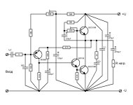
Some people suggest connecting negative to the emitter of the lower output bipolar transistor. This is where the main current flows.заземление питания
The minus of the second electrolytic capacitor and minus the speaker are also connected there.
In the figure, a different connection point is selected, but this depends on the topology of the board. Helps to avoid main current flow in a weak signal circuit.
Attachments
Last edited:
- Home
- Amplifiers
- Solid State
- JLH 10 Watt class A amplifier