This does not make sense. Please clarify.Samuel Groner looked at this problem in his paper "Audio Power Amplifier Design Handbook" by Douglas Self
Samuel Groner looked at this problem in his paper "Audio Power Amplifier Design Handbook"
1) All transistors have different characteristics and distortion spectrum.
2) Distortion depends on the circuit and the mode of transistors.
I was talking about Early Effect which was discovered by George Early who described a feedback issue within a transistor operating as a common emitter stage due to base width modulation. The problem is due to the fact that there is capacitance in the collector to base diffusion which changes inversely according to the square root of the voltage applied to the collector - the width of the diffusion is representative of the level of collector to base capacitance.This does not make sense. Please clarify.
When a.c. current is drawn through the bootstrap capacitor the width of the diffusion i.e. collector to base capacitance will change and this will be dumped to the base of the common emitter stage. The preceding input transistor common emitter stage and this will have to handle the variations of the Vas stage input load.
When high levels of current are drawn from the supply the voltage between the supply rail and the collector will drop a lot of voltage and that at the Vas collector will be very compared low compared to rail voltage so the capacitance and width of the diffusion will increase. This changes the relationship between the collector and base as the diffusion between the collector and base will result in a small measure of base expansion into former collector territory and a reduction in current gain for the Vas transistor.
This is not a huge issue as Bailey noted as his circuit performance was reduced by about three times what he expected with the planar transistors he used. His graphs showed at 10W and 30W rms into 8R THD from 0 -20kHz remained below 0.1% over most of the range reaching 0.1% at 20kHz. He would have predicted 0.033%. The best Vas transistor he had tried for these results was 40362 by RCA. By todays standards these figures are fairly mundane due to improved circuit design.
Silicon Chip magazine published a Blameless circuit in December 2021 where options for Vas transistors were tried. The best results were achieved with KSC3505S and BF469. Slightly elevated results were achieved with BD139 but noted there are many types of the latter out there. BF469 is hard to find however Jaycar Electronics sells a version of this which is possibly from a second source supplier like CDIL. MPSA42 was OK but unsuited for use in the JLH design due to power handling limitations.
I cannot say anything better than what is stated in the introduction on the first page of the paper. All that was required was to click on the link provided in my post to read this.If that means that Mr Gronsr has written a paper about Mr Self's book, it would be handy to say so clearly.
Indeed, it does mean that Samuel Groner wrote a paper about Douglas Self's book(s), specifically "Audio Power Amplifier design Handbook - 5th Edition" and there was a flurry of interest here at diyAudio when it was published. Being a forum, most information and comment soon gets buried here as yesterday's news but it's not difficult to reference the paper from a number of sources: https://www.diyaudio.com/community/...ifier-design-handbook-by-douglas-self.183146/
Last edited:

Silicon Chip magazine published a Blameless circuit in December 2021 where options for Vas transistors were tried. The best results were achieved with KSC3505S and BF469. Slightly elevated results were achieved with BD139 but noted there are many types of the latter out there.
Any, even the simplest simulator without complex scientific research, makes it clear that the best transistor in a cascade VAS is a composite assembly of 2, 3, 4, and even 5 transistors. Quality grows from quantity in a logarithmic relationship. However, for a decade now, the selection of components for such a simple solution has been going on, and It looks more like a sporting interest.
A stable current source instead of a bootstrap circuit solves this problem.When a.c. current is drawn through the bootstrap capacitor the width of the diffusion i.e. collector to base capacitance will change and this will be dumped to the base of the common emitter stage. The preceding input transistor common emitter stage and this will have to handle the variations of the Vas stage input load.
I built the 1969 circuit with bootstrap collector load. Later I built the 1996 version with a modified current source and direct coupling of the output bringing the transistor line up from 4 to 5.Any, even the simplest simulator without complex scientific research, makes it clear that the best transistor in a cascade VAS is a composite assembly of 2, 3, 4, and even 5 transistors. Quality grows from quantity in a logarithmic relationship. However, for a decade now, the selection of components for such a simple solution has been going on, and It looks more like a sporting interest.
A stable current source instead of a bootstrap circuit solves this problem.
The additional PNP transistor is mounted on the output heat sink to monitor the temperature rise to prevent output standing current getting too high. If the heat sinks are under specified for heat dissipation then the output standing current can be reduced by adjusting a trimpot.
Heat from mounting on the heat sink will increase the current gain in the PNP transistor and result in a reduction of base current for T2 through bypassing the collector base junction of T2. The charge carriers flow in the opposite direction to where the arrow representing the emitter points.
The best Vas for a Class B design needs a buffer stage for the LTP if the dominant pole capacitor is connected between the collector and base of a single Vas transistor because such capacitance will be amplified and dumped at the input of that single transistor. A buffer transistor is necessary for the LTP accordingly.
There is no need for such a capacitor in the JLH because the dominant pole is set by the output transistors which have low bandwidth compared to small signal stages. A Self style Vas is unnecessary
The best Vas for a Class B design needs a buffer stage for the LTP if the dominant pole capacitor is connected between the collector and base of a single Vas transistor because such capacitance will be amplified and dumped at the input of that single transistor. A buffer transistor is necessary for the LTP accordingly.
True, but in the case of progressive correction, there is no capacitor between the base and collector of the transistor VAS, but the buffer is still needed. It is necessary to increase the depth of the negative feedback and, as a result, linear amplification in the operating frequency band until the negative feedback is covered.
There is no need for such a capacitor in the JLH because the dominant pole is set by the output transistors which have low bandwidth compared to small signal stages.
Shiklai's VAS usual assembly gives a significant increase in quality for the circuit. And the use of a nonlinear input capacitance of power transistors as a correction is, excuse me, bad manners in designing amplifier circuits.
One day I made JLH and was so happy to hear so mush details in music. Then I wrote a thread about it. And some guy told me to try Nelson Pass's Aleph J. Since that moment my life changed) I have already made AJ, F4, F5, F6, F7, ACP+, B1. So I want to be that guy for topic starter) JLH is just a step on the stairs of A Class Beasts) Just try AJ.
True, but in the case of progressive correction, there is no capacitor between the base and collector of the transistor VAS, but the buffer is still needed. It is necessary to increase the depth of the negative feedback and, as a result, linear amplification in the operating frequency band until the negative feedback is covered.
Shiklai's VAS usual assembly gives a significant increase in quality for the circuit. And the use of a nonlinear input capacitance of power transistors as a correction is, excuse me, bad manners in designing amplifier circuits.
I suggest you access Nelson Pass website and look up his PLH design to read his comments about the JLH Class A design and then eat humble pie.One day I made JLH and was so happy to hear so mush details in music. Then I wrote a thread about it. And some guy told me to try Nelson Pass's Aleph J. Since that moment my life changed) I have already made AJ, F4, F5, F6, F7, ACP+, B1. So I want to be that guy for topic starter) JLH is just a step on the stairs of A Class Beasts) Just try AJ.
So I want to be that guy for topic starter) JLH is just a step on the stairs of A Class Beasts) Just try AJ.
I do not share your optimism, because in the modern world, to admire the audio sound of a circuit with an electrolyte in the emitter circuit of the input transistor is, excuse me, "a step into the underground" ...
I, too, am into maximum sound. For me, listening to music poorly is too much of a waste of time. And the knowledge that I'm listening badly also takes away my joy.
So away with stuff like complex push-pull desigs (Accuphase, Krell... endless list) as example, but also with circuits that have fatal mis-sound-solutions - or a solution of these;-)
So away with stuff like complex push-pull desigs (Accuphase, Krell... endless list) as example, but also with circuits that have fatal mis-sound-solutions - or a solution of these;-)
the most complex mode of operation for a single pair of power bipolar transistors is single-ended in class A, this is done in JLH 1969.So away with stuff like complex push-pull desigs (Accuphase, Krell... endless list) as example
Just try it.I do not share your optimism, because in the modern world, to admire the audio sound of a circuit with an electrolyte in the emitter circuit of the input transistor is, excuse me, "a step into the underground" ...
thanks, but for me this is already a passed stage (see attachment) getting a serious sound from JLCH will not work in principle, but something can be improved, so try to improve something ...Just try it.
Attachments
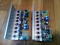
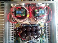
Something to improve: connect the double-mono-psus together, first.thanks, but for me this is already a passed stage (see attachment) getting a serious sound from JLCH will not work in principle, but something can be improved, so try to improve something ...
- Home
- Amplifiers
- Solid State
- JLH 10 Watt class A amplifier