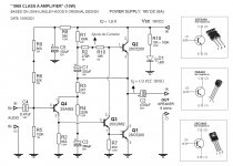
TEST 4 - My JLH 10W (1969) 18V DC and 1,8A
Hi guys, another test of my JLH amplifier. I will do monoblock.
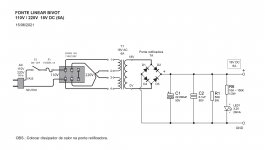
Power supply
Transformer: 110 / 220V • 18V AC
Rectifying bridge: 7A
Capacitor: 22,000uF (63V)
Capacitor: 0.1uF (104)
Resistor: 6k8 (10W)
Amplifier
Power: 18V DC
IQ = 1.8A
Speaker = 6 ohms (50W)
Class A amplifier.
Electronic Engineer John Linsley-Hood Circuit 1969.
TESTE #4 - Amplificador CLASSE A - JLH 1969 (10W) 18V DC e 1,8A - YouTube
Hi guys, another test of my JLH amplifier. I will do monoblock.
Power supply
Transformer: 110 / 220V • 18V AC
Rectifying bridge: 7A
Capacitor: 22,000uF (63V)
Capacitor: 0.1uF (104)
Resistor: 6k8 (10W)
Amplifier
Power: 18V DC
IQ = 1.8A
Speaker = 6 ohms (50W)
Class A amplifier.
Electronic Engineer John Linsley-Hood Circuit 1969.
TESTE #4 - Amplificador CLASSE A - JLH 1969 (10W) 18V DC e 1,8A - YouTube
ST and Motorola 2N3055's were OK. Now of course ST has obsoleted it but still available from ON semi. You should be able to get a genuine 2N3055 from them through reputable dealers (e.g RS or Farnell in the UK).
but 2SC5200 is faster and should be acoustically superior.
There may be fake 15003's out there too as well as 3055's.
2SD882 seems overkil for driver. It has a high current rating (3A?) and suggests that the chip will have a high capacitance.
The BD139 may be a larger chip now than the original, and disconcertingly the fT is no longer on some datasheets. As I've posted before, measured ft's of ON Semi and ST devices are in the region of 100MHz. I've used it in some JLH69's, without a problem, but a smaller device with less Cjc would be better, I'd agree.
With 2SC5200's the gains are high and a lower power transistor may be sufficient.
Do your 5200's have a gain group suffix?
If minimum, hfe=55 at 1A, then your driver needs to work at around 20mA or slightly higher (worst case). With 30V supply that is 300mW, so a small signal TO-92 2N4401 might be OK on most (i.e. typical ) devices but I'd attach it to as small heatsink. Perhaps a BC337 would also work.
Thanks for this information, John!
I am using TTC5200(Q) from Mouser, but I could not find hFE differences between various suffixes.
I am still wondering if 2N4403 and 2N4401 are good substitutes for 2N3906 and 2N1711? However, I can still get 2N1711 if they are better. How about TIP41C, which is supposed to be very linear?
The parts have arrived. 2SC5200 and everything I need for the stereo(dual mono version).
Project restart:
Driver 2SD882, input 2N2907 or BC560, 1 heatsink/1 5200, psu 7824 based.
Hi, I see you received 4 power transistors. I have a kit, came with 4 2SA1216.
Did you test your transistors for matching before assembly? Or didn't you care about that?
Are you using 2SA992 (Q4) and 2SC2682 (Q3) as shown in your schematic? No trimmers for mid-point and Iq adjustments?
Hello Hanair, yes I am using 2SA992 (Q4) and 2SC2682 (Q3) in my circuit, as per the diagram. I live in a coastal city here in Brazil, and in my region there is a lot of humidity. And the components rust very quickly. That's why I'm not using trimpots for current adjustment and VE adjustment according to the scheme.
After several tests, I arrived at this configuration that is in the schema. I powered my circuit with 18V DC. My speaker is 6 ohms. For me to have a PURE CLASS A, I need the speaker to pass all the current it needs. In my case: in C2 (4,700uF) it is + 9V and - 9V. With the following formula it is: 9V/6 ohms = 1.5A
I need a current of at least 1.5A to pass through the speaker so that I have a PURE CLASS A.
With that I was adjusting R2 and R10.
Current stabilized at 1.8A
Then for the VE adjustment (1/2 VDC) I adjusted R6 and R9. I managed to leave it at the right tension.
In practice it was:
VDC = 18.40V
VE = 9.20V
IQ = 1.76A
My TRAFO:
110/220V 60Hz
18V AC (6A)
Attachments
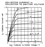
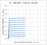
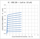
Here are early/first generic 2SA992 IV curves from my homemade curve tracer.
My next step is to add amplifiers after the DAC (along with a new power supply) to extend the voltage and current range of the measurements. I am still thinking about the best way to do that. For now it only covers a small region of current and voltage. [So I plotted the results twice for easier comparison to the NEC datasheet curves.]
My next step is to add amplifiers after the DAC (along with a new power supply) to extend the voltage and current range of the measurements. I am still thinking about the best way to do that. For now it only covers a small region of current and voltage. [So I plotted the results twice for easier comparison to the NEC datasheet curves.]
Attachments
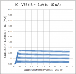
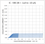
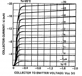
Here are early/first generic 2SB737 IV curves from my homemade curve tracer.
I am interesting in interpretations of the differences (compared to the Rohm datasheet IV curves) even though I have not yet gone to higher collector currents yet.
I am interesting in interpretations of the differences (compared to the Rohm datasheet IV curves) even though I have not yet gone to higher collector currents yet.
Attachments
Hi guys, my JLH is ready.
Monoblock.
Transformer 110/220V 60Hz: 18V DC (6A)
Amplifier: 18,30V DC
I.Q.: 1.75A
Speker: 6 ohms.
TESTE #5 - Amplificador CLASSE A - JLH 1969 (10W) 18V DC e 1,8A - MONOBLOCO - YouTube
Monoblock.
Transformer 110/220V 60Hz: 18V DC (6A)
Amplifier: 18,30V DC
I.Q.: 1.75A
Speker: 6 ohms.
TESTE #5 - Amplificador CLASSE A - JLH 1969 (10W) 18V DC e 1,8A - MONOBLOCO - YouTube
Hi. I finally got around to working on my first amp board for my JLH 69. It is the first time following a schematic and making a circuit from scratch. I tried to place the components perpendicular to each other as much as possible. I would like to test it but I only have an unregulated benchtop power supply. Would this be ok for testing purposes?
Attachments
![20210903_064619[1].jpg](/community/data/attachments/896/896259-d00acb6d2eb87f7024caca3ec9eaacbd.jpg)
![20210903_064625[1].jpg](/community/data/attachments/896/896280-7fbb8477431304ae29b6bf8ac4b3d457.jpg)
The power supply is needed for a voltage of 12v (20-27v) and a current of at least 2A (for one channel) - power 40 watts. If the power supply is unstabilized, an electrolytic capacitor of 10,000 microfarads or more will be needed (not required for SMPS). #8107
My old lab power supply goes up to 30VDC and 10amps. If I were to hook it up to an 8ohm load and power it with a voltage similar to what I can expect from my transformer (minus losses for regulation and filtering) with a 10000uf cap and have the output transistor on a heat sink then I should be able to hook up a 2v "line out" input and set bias and get an indication of the performance of the single channel?
You do not need to connect a large capacitor to the laboratory power supply. Use short wires and a 2a fuse. Recommended JLH voltage 27V / 1.3A DC at 10W / 8 ohm. The first turn-on can be done at 12v. The output transistors must be mounted on large heatsinks using thermal spacers and thermal paste. The input voltage is less than 1V, so a 10k potentiometer is needed to adjust the level.
Last edited:
RIPPLE
Vpp = I/2fc = 1A/100 ( Hz ) x 10000 uF = 1/1 = 1V peak to peak. 60 Hz is slightly less at 0.83 Vpp. 3/2.5 Vpp at 3 amps. For a bridge rectifier.
From memory the JLH has about 40 dB PSU rejection ( not bad ). It suggests hum will be noticable and not much better than -40 if using up to 3 amps. -80dB is ideal and - 60 dB usuable but not really hi fi. I usually assume reference 1 watt. 2.83/1000 = 2.83 mV rms for - 60 dB hum.
10 000uF good as a starting point. It ensures the capacitor has a long life.
This is a little bit like a JLH PSU of JLH. He didn't use the Zener diode. Above is the capacitor. Below the very simple regulator. The simplicity should sound good. After all it's an extra amplifier. It helps to be fast. I didn't do much better using a slow LD1084.
This is a low loss version like a LD1084. The transistors were junk box specials. Be careful as it can go unstable. The simple NPN NPN darlington is more stable. A ready made darlington will have feedforward resistors. Hard to say if that's best. It speeds up the working.
NOTE 90 000 uF. Not doing enough really. The voltage is not really a factor for this study of working. It's the amps. Just over 1 amp here.
Last edited:
Fair point. The diagram was from me to me really. I mostly would be careful of the complimentary pair. The PNP isn't the best choice. 2SA1943 could work. If a series resistor is fitted make sure it isn't too big. 2SC5200 as TR1 could work and should be bullet proof. That combo might be very nice and low cost.
The LD1084 is mostly a LM317. It is very well behaved. A LM317 with PNP pass device if an oscilloscope used can outperform most things. 2N2955 was typical and should be fine with 2SA1943.
My previous post was to show how poor a 90 000 uF capacitor is if no regulator used. It's the type of regulator I was told not to bother with in 1974 at college. In that example it is reasonably good. The JLH design should be similar.
If I remember LD1084 is OK above 24V as long as it never sees a short circuit ( read up ) . Their is a 317HV.

I found some LD1084 notes I made to myself so please keep that in mind, not made for here. The layout is easilly worked out from the application notes and follows LM317. In some ways this betters when the unit is switched off due to device output impedance. The PSU was a ground plane type. The fuse between 2 x 10 MF slightly helped things in the upper audio band ( 3 dB ? ). The diodes at the input worked better than I guessed. Usually I use soft recovery types.
The hum is about 20 dB better than a simple layout. The oscilloscope made the difference as to where grounds were fixed ( rebuild ). The measurements are refered to 12VDC.
With minimal complexity LD1084 works well and is a good benchmark. I would use 2 for 5 amps, one left and one right. A TL431 and darlington not quite as good. ON semi for those.
A Meanwell SMPS is about -80dB in general with peaks at - 65 dB. Filtering didn't change it as much as I hoped. The noise was 10 kHz to 20 kHz at the current I used. A DC input filter didn't do much when 220 uF.
If we liken the 2 x 10 MF to a strorm at sea the LD1084 as a harbour is mirror flat inside the harbour. Notice I use 470 uF on the voltage setting arm. 10 uF is good enough. If fitted the PSU takes time to rise which could be a good thing. I didn't notice a downside.
https://www.ti.com/lit/ds/symlink/lm1084.pdf?ts=1630786374737
- Home
- Amplifiers
- Solid State
- JLH 10 Watt class A amplifier