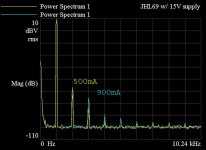
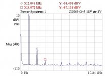
I ran distortion curves last night, +10dBV into 20 Ohms. At 500mA static current, H2 was -74dB, H3 was -90. Increasing current to 900mA lowered H2 to -79 but raised H3 to -81 and brought higher harmonics out.
Not great resuts. There's a ground loop I need to fix, that should improves things some. Also the bench power supply I'm using has high-ish output impedance, 3mVRMS of ripple at the test freq appears on the rail. I'll try another one.
Not great resuts. There's a ground loop I need to fix, that should improves things some. Also the bench power supply I'm using has high-ish output impedance, 3mVRMS of ripple at the test freq appears on the rail. I'll try another one.
Attachments
That's exactly what it should be.
I assume you mean the 500mA one?
Jean Hiraga thinks to the ear this sounds like zero distortion. I agree. At higher voltage you might have a lower THD.
Well Jean can have his opinion, but that's another matter. I will also be trying a higher supply voltage (18-24V) and see what that changes, if anything.
Saying Jean can have his opinions is a bit like saying what did Einstein know.
The 500 mA isn't very important. It's nice to see it hasn't changed the harmonic progression. Hiraga was the first to really pin down distortion and the ear mechanism. He says should the distortion follow a suspension bridge type curve the ear will like it. 1% THD with a curve like that would sound undistorted. Sometimes one would guess 0.001% if you didn't know. It's a relativity of sorts.
The 500 mA isn't very important. It's nice to see it hasn't changed the harmonic progression. Hiraga was the first to really pin down distortion and the ear mechanism. He says should the distortion follow a suspension bridge type curve the ear will like it. 1% THD with a curve like that would sound undistorted. Sometimes one would guess 0.001% if you didn't know. It's a relativity of sorts.
Is that supposition valid only for a single instrument and a single tone at a time? With a mix of a large number of instruments and tones does that turn into a forest of distortion products? Maybe that sounds ok with piano or acoustic guitar. Perhaps with dense mixes it does not sound ok?
Is that supposition valid only for a single instrument and a single tone at a time? With a mix of a large number of instruments and tones does that turn into a forest of distortion products? Maybe that sounds ok with piano or acoustic guitar. Perhaps with dense mixes it does not sound ok?
With a dense spectrum and compression, there is not enough power. Of course, taking into account the sensitivity of the speakers.
Last edited:
I did the test again today with a better supply and no ground loop. The test freq ripple on the rail disappeared, but there was no change in the distortion measurement. I may experiment with different sets of output transistors just to see what happens. I have a bunch of TO-3 NPN's scavenged over the years from amps, power supplies, active loads, and other industrial gear to play with.
An op amp with booster transistors is another way. 7 Vrms is possible. I used two feedback loops so as to have some feedback directly to the op amp. OPA604 at the time
A class AB output can be made class A up to loud enough. It then becomes AB after that. This keeps hum low as music will mask it when we distort. If the outputs have high current gain the op amp will work in class A. This could sound better.Ears clip.
This is looking increasingly like it may be the way to go. What I really need is a low-gain buffer. 8-10dB of gain delivering 5W into 18-20 Ohms. I do not need the 24+ dB of gain that all these amps are designed with.
There is a proposal to assemble a temporary circuit without the first (input) transistor and GNFB (#7755). Make an offset to the base of the second (driver) transistor. Submit a test signal there through an electrolytic capacitor of 50 microfarads. Save the base-to-ground resistor (8k2) and add an 82k resistor to the (+) bus.
The measurable changes when replacing transistors will be more noticeable. DC mode will remain.
The transistors must be preselected by the gain on direct current at three points (1/10, 1 and 2) of the quiescent current. Use heatsink.
A test standard circuit with a common emitter and 10 ohm collector load can be assembled to evaluate the distortion and frequency response of single power transistors.
Use the transistor with the best frequency properties as the lower one.
Last edited:
#7770
The output transistors must be placed on the radiator, the quiescent current should be about 150mA.
And it was the AD744 + repeater that made it possible to get the distortion level below -120 dB.
The device is powered by two LM317-337 voltage stabilizers.
Усилитель для наушников на AD744 с буферным каскадом — audiohobby.ru
Last edited:
Build the (Class A) WHAMMY with a BJT output stage. Thanks to the push pull followers, 300mA of DC bias will let you push ~550mA peak into your 20 ohm load, while never departing from class A. That's a peak signal swing of 11V at the load, i.e. 7.8V RMS. Using a 30V supply rail your total power consumption is 9 or 10 watts per channel. Pick an opamp whose output current dramatically exceeds (550mA / Beta); AD817, OPA209, AD825 come to mind.
Gain as drawn is +15.2dB, which you can lower by modifying R8 & C7.
A single feedback loop encloses the entire "composite amplifier", i.e., both the opamp and the discrete power buffer.
Gain as drawn is +15.2dB, which you can lower by modifying R8 & C7.
A single feedback loop encloses the entire "composite amplifier", i.e., both the opamp and the discrete power buffer.

Build the (Class A) WHAMMY with a BJT output stage.
Yes, something along those lines. Not using a 2604, though...
Since it is here before me right now, I'm going to see how low the gain of the JLH can go and maintain stability, via raising the shunt feedback R. Distortion should benefit from it, as well.
@OLDDiy, thanks for your suggestions re: testing the output transistors. The AD744-based circuit appears to be an inverter.
Last edited:
It can be made very simple. I used a complimentary feedback pair as this has very low distortion. BD139/140 might be OK if a higher grade for all. Bias was 2 x 1N4007 and a resistor. 1R emitter resistors. Two identical feedback loops. The doubt is the feedback pair. It measure very well indeed. To be honest the output loop might not be needed for headphones. The bias level was about 1.4V. I guess the resistors used 10K. The rails were +/- 15V. I used 2SA1943 2SC2500 with BD139/140. I glued the 1N4007 to each power device with epoxy. I lost this data so as best I remember.
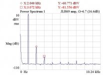
Lowering the gain is worthwhile. With feedback shunt R of 470 Ohms, Gain=6.7, about half the stock setup. Attached is distortion at 1K and +10dBV. With 500mA static current, compared to stock, distortion is lower by 2.5dB at H2, and 2.9dB at H3. Transient response shows no significant difference. Noise is lower as well, but I didn't measure the difference. I see no signs of instability.
Good news for folks who want to go directly from say a DAC output to amp input.
Good news for folks who want to go directly from say a DAC output to amp input.
Attachments
Some more interesting results. Same setup as previous except where noted.
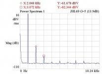
First is with gain of 5. H2 and H3 drop about a dB from G=6.7.
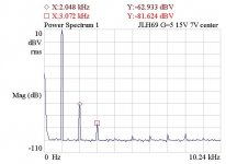
Second is with the output center point set to 7V. H2 drops 1.5dB, H3 is up a dB.
Third is with 18V supply, 620mA static current, 8V center point. H2 drops another db, H3 drops 6dB.
Question: when the distortion drops by changing the output center point does this suggest that the output pair beta are not well matched?
Attachments
The center point does not necessarily represent the minimum distortion at a level close to clipping. Rather a guideline for simple setup without measurements 
The amplifier is unbalanced. Transistors work in different ways. In (+), the CE-CC scheme is formed. In (-) transistors work as CC-CE.
In your experiments, distortion is reduced by increasing the depth of the nfb.
Transistor matching is easier to evaluate without gnfb (# 7771).
The amplifier is unbalanced. Transistors work in different ways. In (+), the CE-CC scheme is formed. In (-) transistors work as CC-CE.
In your experiments, distortion is reduced by increasing the depth of the nfb.
Transistor matching is easier to evaluate without gnfb (# 7771).
Last edited:
The center point does not necessarily represent the minimum distortion at a level close to clipping. Rather a guideline for simple setup without measurements
Understood, and I appreciate your reply. But the reason I'm building headroom into the system is precisely to *not* operate close to clipping. So I still find this phenomena interesting, and wonder what it might be indicative of.
In your experiments, distortion is reduced by increasing the depth of the nfb.
Aye.
Transistor matching is easier to evaluate without gnfb (# 7771).
True, but I'm not trying to use this as a transistor tester, only trying to suss out what the improvement that comes from the asymmetrical "center" point is correcting, or indicative of.
This is the first measurable indication that there is some benefit to a higher operating voltage and current. I'm going to build the 2nd amp for G=5 and do some listening tests.
- Home
- Amplifiers
- Solid State
- JLH 10 Watt class A amplifier
