@chumingo
The circuit oldDIY posted could be used as a template for a low power headphone version.
Perhaps this needs another thread.
For headphones, I don't think you would need more than 1W per channel, if that.
First question - what is the power that your headphones are rated at? ANd what impedance? I've seen 32 to 64 ohms with several being around 40.
A design using BD139/BD140 output transistors would be able to provide 1W into 50 ohms, and run from a single 24V rail or 12+12 split, or simply target a lower voltage (18V or +/-9) for 0.5W, for example.
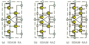
I'd think that the diamond buffer would work well. Though I would be tempted to use lower current for reduced noise, but that depends on the loading required.
Are Diamond buffers particularly picky with regards to supply noise and stability?
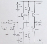
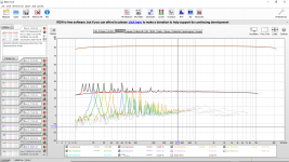
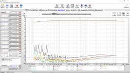
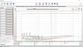
I ask due to the enclosed REW distortion measurements from my in-progress Diamond buffer for my JLH. The first distortion measurements show what I believe was instability and the second shows the improvement when a large (18 nF) cap was added from the 100 Ohm to ground. The third shows a big boost in the local supply bypass capacitors.
There is still what appears to be 60 Hz (showing up as 2nd harmonic of 30 Hz, 3rd harmonic of 20 Hz, etc.) The power supply is LM317/LM337 with bypassed adjustment terminals and large/good quality bypasses on the inputs and outputs of the regulators.
Out of the four types of transistors I have tried so far my best results are from generic 2SC2240 & 2SA970.
Attachments
-
 Diamond Buffer 2SA992 2SC1845 Schematic.png168.8 KB · Views: 659
 -
 20201105 Diamond Buffer Distortion Possibly Unstable.png241.9 KB · Views: 626
 -
 20201105 Diamond Buffer Distortion Add 18nF To Ground From 100 Ohm Input.png229.5 KB · Views: 504
 -
 20201105 Diamond Buffer Distortion Changed Local Supply Bypass to 330 uF.png224.8 KB · Views: 620
As you only need to balance the supply voltages, how about just adding a 78L12,79L12 in the appropriate supply rails with a diode or two and bypass caps for good measure. I don't think HDAM circuits have much to offer here in comparison to a diamond buffer and you would still need to balance the supplies.
Since the Diamond Buffer is running from LM317/LM337 already I was suggesting replacing R1 and R4 with current sources.
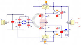
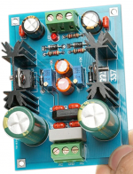
I think the LM317/337 is better than 78L12/79L12. I have attached the picture and schematic of the supply I am using. I originally thought my LM317/LM337 supply would be more than sufficient for this project.
I can try to adjust the 3296W trimmers again to match the supply voltages more closely.
Do I need to go further on the supply and use an op-amp for tracking? If that is the case would replacing R1 & R4 with current sources/sinks be more effective?
Attachments
Last edited:
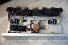
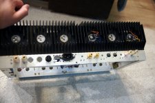
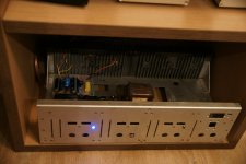
I've always wanted to try the famous Jlh 1969 - now it's almost ready in my test chassis. Input transistor BC560, phase split / VA - BD139. Output BD911 - selected from 10pcs 4 with the highest and equal Hfe. (I tried others salvaged transistors too - there is no BD 911 in the picture). The second channel will be completed tomorrow.Bias with standard values = around 1,1 A. CRC filter - NOS 20 year old daewoo 3x4700 1R 3x4700 + 2200 on the board. Output C = 4700uf. input C - 3uf3. 24V power supply. No hum - silent amp and sounds nice even with one channel. 
Attachments
......then I guess you have no problem with adjusting the supply rail balance, assuming your settings are stable over time/temperature.Since the Diamond Buffer is running from LM317/LM337 already......
The hum and noise residuals appear to be higher than I'd hope for though. Are the LM317/337 genuine parts?
I don't know if they are genuine since it was a DIY kit. On my next Mouser or Digikey order I will add a couple to be sure.The hum and noise residuals appear to be higher than I'd hope for though. Are the LM317/337 genuine parts?
Have you heard of poor performance "generic" or clone LM317/LM337?
One of the TO-220 tabs is rather thin looking. Thinner than I have ever seen out of an authorized distributor.
@kozard- diamond buffers are subject to transistor noise as are all transistor (and other electronic) circuits. But perhaps that was a bit of a red herring as it will be operating at a fairly high level (maybe around a volt) so added noise would probably not be too noticable.
If anything, I think the effective parallel operation of the NPN/PNP pair should reduce the noise (by a factor of root 2) compared with single devices, but having two stages would counter that, so not much different from a single stage, perhaps, though I haven't investigated.
I notice that you have no emitter resistors in your circuit in post 7364. They may help to linearise the circuit and allow you to operate with some current gain which may help to keep noise low (by allowing the front pair to operate at a lower current).
Maybe help with stability too.
Indeed. A quick sweep of problems goes back decades and the craziest fake example is a TO220 shell with just a resistor inside. Others usually have undersized power transistors and short-form opamp circuits based on a simple pair of opamps and good for less than half their expected ratings but for audio, the more important good regulation and PSRR properties will be far less than expected.......Have you heard of poor performance "generic" or clone LM317/LM337?
One of the TO-220 tabs is rather thin looking. Thinner than I have ever seen out of an authorized distributor.
Regarding thin backplates, I now see this is with a number of TO220 transistors too. I also read a supplier doc. recently that claimed this was to facilitate soldered, surface mounting as well as through hole, bolted assembly and more or less asked the question "who needs a thick backplate anyway? That just made me wonder what you do when you pull down on a silpad insulator and buckle that thin backplate or ask yourself just what were TO252, DPAK etc. packages meant for?
.Well I dug through my boxes of parts and found some genuine National LM317 from about 30 years ago.
So what I will try to do is use REW in RTA mode to plot a spectrum of the power supply (only) output noise with the DIY supplied regulators and then a second LM317 supply with one of the genuine National LM317 installed. If that does shows a problem with the LM317 or LM337 in the power supply I will get genuine Ti LM317/337.
If that does not show a problem then I will try improving the PSRR of the Diamond Buffer by replacing the bias resistors with current sources. Instead of the linear dependence on power supply voltage the current sources should bring a big PSRR improvement, right? If I bypass the LED at the base of the current source transistor that should help more I hope.
Speaking of that thin tab LM317 I just received another one yesterday. This time it is in the power supply for the NE5534/MBL6010 clone pre-amp. I will have to check those NE5534 for slew rate and the output follower voltage waveform signature against a reference real NE5534... ...just in case. And I can measure the output noise spectrum of that power supply at the same time as the Diamond Buffer power supply.
Last edited:
Another Diamond Buffer circuit is the "Austin" input stage daughter card for the First Watt power amp called M2x. Schematic below. Quite a few diyAudio members have built and are listening to "Austin". It's one of the PCBs the diyAudio Store ships you when you buy the M2x power amp board-set.
Yes, it's AC coupled.
_
Does anyone have sharable Eagle files or order-able and sharable Gerber files for a Diamond Buffer such as the Austin buffer or a similar one? Or pcbCAD720?
I would like to make a PCB based preamplifier for the JLH with the volume potentiometer followed by a nice Diamond Buffer. I am going to try to order from JLCPCB. My target is a standard size 100x100mm board. The volume potentiometer can be on the board or separate.
So far my Diamond Buffer experiments have been on prototype boards.
I built aliexpress white jlh boards. Used new onsemi n3055 outputs.Power supply is 4*22000uf caps with 23vdc each channel. Bias is 1.6A. I'm testing the amp with BA3 preamp. Nothing exploded yet but I have high hissing sound increases with volume level on BA3 preamp. Any idea where to check?
Hmm.. Reversed channels from pre and noise jumps to other channel. It comes from BA3.
Hmm.. Reversed channels from pre and noise jumps to other channel. It comes from BA3.
Last edited:
"The circuit also matters 2003 (– Tim Andrew ‘JLH for ESL’ circuit)provides more power.
BeforeTim first contacted me, he had built a kit version of the 1996 design, which he had subsequentlyupgraded with higher quality components. Though Tim was happy with the results, he was keento see if further improvements could be made to the sound quality and I was pleased to be ableto suggest various circuit modifications, the majority of which subsequently proved to be veryworthwhile. Each of the modifications was carried out separately so that the results could beevaluated on an individual basis".
(PDF) Jlh-2003-amplifier | adolfo martinez - Academia.edu
Can work with load less than 4Ω. It reproduces infra-low frequencies better. Developed for ESL control. More power - more radiators, dimensions and weight. The implementation is more complicated, more expensive. The setup is more difficult. Requires experience.
1969 with a simple scheme requires the selection and use of quality parts. Execution matters. For quiet listening to vocals, solo instruments and jazz.
2003 (– Tim Andrew ‘JLH for ESL’ circuit)provides more power. BeforeTim first contacted me, he had built a kit version of the 1996 design, which he had subsequentlyupgraded with higher quality components. Though Tim was happy with the results, he was keento see if further improvements could be made to the sound quality and I was pleased to be ableto suggest various circuit modifications, the majority of which subsequently proved to be veryworthwhile. Each of the modifications was carried out separately so that the results could beevaluated on an individual basis".
(PDF) Jlh-2003-amplifier | adolfo martinez - Academia.edu
Can work with load less than 4Ω. It reproduces infra-low frequencies better. Developed for ESL control. More power - more radiators, dimensions and weight. The implementation is more complicated, more expensive. The setup is more difficult. Requires experience.
1969 with a simple scheme requires the selection and use of quality parts. Execution matters. For quiet listening to vocals, solo instruments and jazz.
Last edited:
- Home
- Amplifiers
- Solid State
- JLH 10 Watt class A amplifier