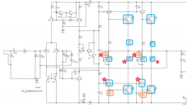
A comment on the schematic - Don't believe all that you see of published LJM schematics. There were more obvious, intentionally messed up diagrams shown here in the past, so if you see something anomalous, don't trust the schematic, check the PCB. It is sad to see this type of disinformation in promotional details but the Chinese market is not only very competitive but apparently unregulated and constraints like foreign patents or copyright laws are unknown or simply ignored.
Bona fide engineer/designers like LJM are apparently rare among sellers and I guess they still have to protect their businesses from copycat sellers who just work on-line with PC based methods of duplication.
Bona fide engineer/designers like LJM are apparently rare among sellers and I guess they still have to protect their businesses from copycat sellers who just work on-line with PC based methods of duplication.
Well I finally tracked down all the problems.
The drivers were badly mismatched but the outputs turned out to be pretty well matched when pulled and measured.
At first I put in new 649 drivers which were matched as closely as my meter reads for hFE and Vbe. Did not solve the problem.
I didn't think it would fix it but I then swapped the 649 drivers for genuine TTA004 from Mouser. Again as closely matched as my meter reads for hFE and Vbe. Did not solve the problem. Still badly mismatched bias currents between the two lower K1047/2SD1047.
Next I swapped all four K1047/2SD1047 for four genuine Toshiba 2SC5200N from Mouser. I was lucky and I was able to get two very nicely matched pairs.
Should work great now, right? Very nicely matched genuine drivers and outputs. No, the bias current mismatch is now worse with very closely matched transistors. But I did note that the 2SC5200N exhibits lower thermal resistance (using my IR spot thermometer).
I was starting to run out of components to swap. I thought I would try replacing the 0.22 Ohm resistors since they were how I was measuring the bias current. (And 0.22 Ohm isn't that easy to accurately measure in circuit with my handheld meter.) All I had were 0.12 Ohm 3W Metal Film so I swapped all four 0.22 Ohm 5W Cement with those. That made a big difference. The hotter lower output device dropped from over 300% of the bias (of the colder device) to now less than 200%. One of the 0.22 Ohm resistors was high but not open.
So a big improvement but something else was wrong.
I looked at the schematic and all that was left were four 100 Ohm resistors which measured fine... ...and two 1N4004 diodes.
It turn out that the Vbe of the drivers depends on:
1. The base connection to the bias device which is shared by both drivers. So that is not the problem.
2. The emitters of the two 649 drivers see a different voltage because they go through different 1N4004 diodes that connect to the output. So these diodes must be matched!
So I pulled the diodes and measured them: One measured 564 mV while the other 555 mV!
I measured almost half of my 1N4007 diodes before I found two that measured 603 mV and put those in. Now the bias currents were almost identical. 4.7 mV across one of the lower 0.12 Ohm resistors and 4.6 mV across the other.
Summary of Changes:
1. TTA004 Lower Drivers
2. 2SC5200N Outputs
3. RM065 2k potentiometer in place of lower 2.2 bias resistor
4. 10 uF 50V Nichicon UES input cap
5. Matched 1N4007 diodes for Vbe of lower drivers
6. Replaced 0.22 Ohm resistors with 0.1 Ohm 3W Metal Film
I think it sounded quite nice for the first 40 minute test tonight. I will test some more later this week against the MA9S2 and in the future against the JLH & L7 (the boards are assembled but not placed in a chassis yet).
Just FYI: I was posting in the LJM thread but did not get much for replies so I posted here since I was getting more inputs/answers that I needed. I'll switch back to JLH programming now")
Thank you for all the help!
The drivers were badly mismatched but the outputs turned out to be pretty well matched when pulled and measured.
At first I put in new 649 drivers which were matched as closely as my meter reads for hFE and Vbe. Did not solve the problem.
I didn't think it would fix it but I then swapped the 649 drivers for genuine TTA004 from Mouser. Again as closely matched as my meter reads for hFE and Vbe. Did not solve the problem. Still badly mismatched bias currents between the two lower K1047/2SD1047.
Next I swapped all four K1047/2SD1047 for four genuine Toshiba 2SC5200N from Mouser. I was lucky and I was able to get two very nicely matched pairs.
Should work great now, right? Very nicely matched genuine drivers and outputs. No, the bias current mismatch is now worse with very closely matched transistors. But I did note that the 2SC5200N exhibits lower thermal resistance (using my IR spot thermometer).
I was starting to run out of components to swap. I thought I would try replacing the 0.22 Ohm resistors since they were how I was measuring the bias current. (And 0.22 Ohm isn't that easy to accurately measure in circuit with my handheld meter.) All I had were 0.12 Ohm 3W Metal Film so I swapped all four 0.22 Ohm 5W Cement with those. That made a big difference. The hotter lower output device dropped from over 300% of the bias (of the colder device) to now less than 200%. One of the 0.22 Ohm resistors was high but not open.
So a big improvement but something else was wrong.
I looked at the schematic and all that was left were four 100 Ohm resistors which measured fine... ...and two 1N4004 diodes.
It turn out that the Vbe of the drivers depends on:
1. The base connection to the bias device which is shared by both drivers. So that is not the problem.
2. The emitters of the two 649 drivers see a different voltage because they go through different 1N4004 diodes that connect to the output. So these diodes must be matched!
So I pulled the diodes and measured them: One measured 564 mV while the other 555 mV!
I measured almost half of my 1N4007 diodes before I found two that measured 603 mV and put those in. Now the bias currents were almost identical. 4.7 mV across one of the lower 0.12 Ohm resistors and 4.6 mV across the other.
Summary of Changes:
1. TTA004 Lower Drivers
2. 2SC5200N Outputs
3. RM065 2k potentiometer in place of lower 2.2 bias resistor
4. 10 uF 50V Nichicon UES input cap
5. Matched 1N4007 diodes for Vbe of lower drivers
6. Replaced 0.22 Ohm resistors with 0.1 Ohm 3W Metal Film
I think it sounded quite nice for the first 40 minute test tonight. I will test some more later this week against the MA9S2 and in the future against the JLH & L7 (the boards are assembled but not placed in a chassis yet).
Just FYI: I was posting in the LJM thread but did not get much for replies so I posted here since I was getting more inputs/answers that I needed. I'll switch back to JLH programming now
Thank you for all the help!
Attachments
Last edited:
The designer has chosen to split the Miller capacitor into two, one small one (C7) and a larger one (C4) which is fed from the output rail. This is clearly an attempt to reduce distortion, but would be more appropriate for crossover distortion in a Class AB amplifier.
I assume this design operates in Class A.
So the designer intended Class AB but a few purchasers have noted that the fixed bias of the boards is often nearly zero (as was my case). As a result some of the purchasers have installed trimmers and have adjusted bias while either listening to the results or using a combination of measurement and listening. The result is that a number of purchasers have biased (a variety) of LJM amplifiers much more than traditional AB bias but lower than class A.
If the boards are assembled with fixed bias resistors which result in nearly zero bias current (far below normal AB) then I am not sure that the factory test will do a good job of detecting a variety of bias related issues and causes such as mismatched drivers, outputs, diodes or even a bad emitter resistor.
Interesting that the designer didn't just use common bias rails like Alchemist Forseti ADP20, with a 4 prs CFP output stage. Alchemist Forseti ADP20 schematics
Last edited:
Kozard - regarding Ian's comment, does your PCB match the diagram?
Still, the PCB layout does not appear to allow for thermal coupling between the drivers and 5551 compensator.
Old-DIY -if you operate the design in Class A you probably don't need the Baxandall diode. Other designs have no emitter resistor/diode. I've sometimes used a low value resistor (typically 4.7 or 6.8 ohms) to provide a slight improvement in HF stability and bias stability, but that is also related to the base resistor and maximum expected driver current. 33 ohms sounds too high but I've no doubt circuits using high values exist.
"
As I commented, at the time, the design
gave a somewhat lower distortion if the hFE of
Trl was greater than that of Tr2' This caused
the output circuit to act as an amplifier with an
active collector load rather than an output
emitter follower with an active emitter load.
A simple modification which takes advantage of this effect is the use of a Darlington transistor such as an MJ3001 for Trl'
At I kHz, this reduces the distortion level at just
below the onset of clipping from about 0.1 %
down to nearer 0.01 %. As before, residual distortion is almost exclusively second harmonic.
Also, as before, it fades away into the general
noise background of the measurement system
as output power is reduced.
While this transistor substitution seems to be
a good thing, it was not a modification whose
effect I was able to check, in listening trials,
against the Williamson. As a result, for the
sake of historical fidelity, I would still recommend the use of epitaxial-base 3055s as Trl
and Tr2'
September 1996 ELECTRONICS WORLD
Curious comment. I agree that the distortion will reduce, but using a Darlington for Tr1 will upset the drive balance. Only a small current swing will be needed in the Darlington for a large output swing. Since the drive current has to subtract from the upper transistor (Tr2) that won't change current very much. So it will act more as a constant current source - and therefore limit the output power compared with a true push-pull stage.
Not sure if JLH investigated that.
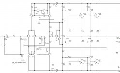
I am using the MX50x2 schematic posted by Rallyfinnen. (The "official" schematic does not match the input section such as the current source biasing with the 5551 transistors as diodes.)Kozard - regarding Ian's comment, does your PCB match the diagram?
Relative to Rallyfinnen's schematic I have not traced it out to check but I did not notice any discrepancies in the values or schematic of the output section while I debugged and rebuilt the entire output section.
Relative to Rallyfinnen's schematic the only discrepancies I found were:
1. The values of the fixed resistors for the bias which did not match what was installed. (For example, my R12 was 2k and bias was near zero. It is now a RM065 series 2k trimmer. I did not have a 2k 3296W.
2. And of course the actual PCB has no trimmer for the bias, which I have fixed.
3. Q6 & Q7 are not 649/669 on my board they are NCC5551 and NCC5401
I bought these assembled to save some time so that I could compare the sound of this design to the others (MA9S2 and the in-progress JLH and L7). In the future I think I will try to stick with DIY kits where I can measure and match all of the components, replace at least the big transistors and solder it properly.
The MA9S2 did not give me such troubles and that was a DIY kit where I measured every single component before soldering.
Now the real question is: Do I dare connect it to the full +/- 50V again? Perhaps with a light bulb in series with the transformer, small fuses and/or large power resistors in series with Vcc & Vee? And a large fire extinguisher?
Attachments
Good question.
I assume you have re-routed the PNP driver emitters to the 0.22 ohm resistors?
I note there is no protection circuitry. You might consider adding something. Often the VAS initiates disaster if it is not current limited. A couple of diodes from base to neg. rail and an emitter resistor would suffice. I usually make the emitter resistor half the value of the one used in the CCS.
Simple current limits often cause less trouble than active limits as feedback in a transistor limiter can cause oscillations, needing capacitors to fix, and depending on how they are added, might increase distortion especially at high frequencies.
One or two diodes in series, connected in reverse bias between the bias regulator and centre rail may help. If the bias voltage is 2.4V (4x0.6V) as an example, it sits +/-1.2V from the centre rail. If a diode is connected anode to the lower bias point (Q9e, Q7c junction) to the centre rail, the maximum voltage the upper point can be driven will be 1.2+.6 or about 1.8V higher than normal. With 0.22 ohm resitors that should allow a lot of amps before protection starts, but if you need more, then two diodes in series will add another 0.6V. You do the same for the upper output devices with another diode cathode to Q9c and anode to centre rail. If you need to limit the current to a lower value, use larger emitter resistors.
If you can simulate this you should be able to determine suitable component values.
This temporary current limit has to be accompanied by a fuse, fast acting.
You could also test the current sharing by wiring up a D.C. bias adjust pot on the input - say a 10k pot fed from +/- 10V Zener stabilised rails and a 10k resistor attached to the negative input side (feedback transistor) not the input - this should keep the base voltage close to zero, (virtual earth) and hence not reverse bias the electrolytic while the output swings up and down (by up to 30V). Use a dummy load not a speaker and measure the volt drop across each 0.22 ohms.
Good luck.
If you have a variac that is useful. I don't, but I built a near equivalent with a +/- 60V tracking power supply which means one control sets both rail voltages.
OK- just catching up with this. On another MX50 thread, it describes this as a 100W class AB design. This topic should probably not be in the JLH class A thread.
In which case, I would say that the input stage should be degen'd, the mirror pair have a small resistor (dropping a few tens of mV) to offset any Vbe mismatches, and the compensation capacitors should work, but whether tested properly I don't know. As mjona suggests, a single cap for C7 would be almost certainly guaranteed to work, but still needs degen input, I suggest, since the Re.C7 sets the upper frequency unity gain point.
The LTP current seems to be 0.6mA nominally. That is too small I think. Slew rate with 100pF is 6MV/s and most amps these days try to be 30MV/s or higher.
I agree with your point about the LTP current it would need to be increased in order to drive the Vas with the increased input capacitance - this due to amplification of C7 if increased to 100pF.
The tail resistor value in Self's Blameless is 150R and in this the frequency pole is dominant as the Vas Miller capacitor value is right.
As a rule ''Cdom" equals being 10 times or more effective than any other poles. If a trial value is wrong then the value of C7 would be increased.
Creation of other poles elsewhere by introducing additional capacitors can erode the prevalence of "Cdom" and in this case the amplifier module blew up.
Kozard - If you have not changed the position of the Baxandall diode/resistors of the PNP drivers to the NPN collectors, I recommend you do so. While I agree that the devices should be matched, and it seems you've done a good job there, there is still a possibility of mis-matched currents if the thermal resistances on the power devices is not the same to the heatsink. In the upper output half, the emitter resistors will share the current properly.
I would also recommend you see whether you can bend a small strip of aluminium to join up the drivers and on-board bias stabiliser.
Are you running this design in Class A or AB?
You will need a huge heatsink for Class A especially at +/-50V. I don't think two pairs of devices will be enough. The typical efficiency of Class A is 30% (may be 35%, depending on power supply voltage, clipping limits etc). So no, I would not run the circuit at 50V in Class A.
100W needs 40V/5A or at least 2.5A standing current in Class A, making the input power 250W. Have a think through what that needs.
The other slight concern is that for real power, transistors need to be spread out along the heatsink. Bunching them close together does not utilise the heatsink efficiently. That means, I suggest, a rather better layout is needed which could have the drivers and output devices on one. Then you would need only a single transistor bias regulator.
Regarding the compensation method, it is following Cherry's approach, which from my investigations is the main reason for reduced crossover distortion in his NFDL amplifier.
The 47pF "output inclusive Miller" reduces distortion. It requires additional capacitance on the collector of the VAS, which this design has, in the form of 47pF capacitors on each driver/output pair. Whether these are sufficient I don't know as I have not run a Tian probe on this design, but I assume the 12pF actual Miller capacitor is for additional stability.
Am I right in assuming the problem you were having was over thermal matching and not HF oscillations?
I do not know if the problem was thermal matching or oscillation. I assume it was not oscillation but I have no proof.
One of the two boards burned up in the first few seconds of running with +/- 50 Volts supplies. (First power up outside of my "easy" +/- 25V debugging setup with LM317/337 supplies.)
That first +/- 50V power up was with the "as shipped" fixed bias which was very low.
The second board survived the first power up of +/- 50V supplies but I was very wary and started to probe the 0.22 Ohm resistors and found very imbalanced bias currents. I have since installed a trimmer for the lower bias resistor and I have rebuilt and matched the entire output section (on the surviving board).
Right now I am running a standard AB bias.
I have not yet changed the position of the Baxandall diode/resistors of the PNP drivers to the NPN collectors. I plan to, however right now I am down to one working board. The vendor told me that they would ship a replacement board after the factory prepares one. Once I get two up and running (with standard AB bias and well matched components) then I plan to go from there with the modifications including the Baxandall diode location and the other recommended modifications.
So the MX50x2 is a little bit on hold until I get the other board. (I have one board working with lots of effort and my prized genuine 2SC5200 batch so I don't want to push my luck with the mods until I have the second working board.)
I do not plan to use the current power supply or heatsink for Class A. I was planning to try higher than typical AB biases but not as far as Class A on this board. But that is in the future. I have a heavier defunct receiver with a large extruded heatsink and a dual voltage power transformer (Onkyo TX-SR707). [It has a high and low voltage setting for the power amp supply using two sets of windings and a relay. I have not seen that before. The high voltage was activated with a H_SEC signal from the micro and a relay.] That large heatsink and the lower voltage (22V?) might be usable for class A but I would need to look into the details.
Right now I want to get the basic designs working properly and then I can compare them. At that point I plan to pick one to dig into more thoroughly. For example, I have the MA9S2, MX50x2, L20.5, L7 and a little JLH. I have the most listening time on the completed MA9S2 and I am currently working on getting the MX50x2 and L20.5 ready for comparison.
The L7 has not been powered up yet and the JLH is in the planning phase.
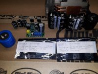
I have enclosed a picture of the collection of available parts for the JLH. I have genuine TIP35, for example. I have lots of genuine 2SA1943 now that so many of the genuine 2SA5200 were used up on the MX50x2 (which was not the plan). I also now have the four D1047 removed from the surviving MX50x2 which could also be tried for JLH. I'll likely try the TIP35 first and leave the PNP conversion with 2SA1943 until later on. I am not very enthusiastic about the D1047 because I would think that even with only one working (the other totally off due to say extreme mismatch) that it should not have burned up. (It was at idle at +/- 50V.) Even with a moderate signal into an 8 Ohm speaker I would not expect a single D1047 to burn up so easily?
Right now I am trying to figure out which of my available caps would be a suitable starting point for the JLH output cap. The JLH board come with a 2200uF 35V Chang branded capacitor. I have a 5600uF 63V BC, 12000uF 35V Nichicon, 4700uF 63V Panasonic and 10000uF 50V Nover. All are power supply capacitors so perhaps none are a suitable series. The first three were bought years ago from a US hobby oriented vendor (BG Micro) and are likely genuine. The Nover came in an audio power amplifier power supply filter board from Ebay so...
One of the two boards burned up in the first few seconds of running with +/- 50 Volts supplies. (First power up outside of my "easy" +/- 25V debugging setup with LM317/337 supplies.)
That first +/- 50V power up was with the "as shipped" fixed bias which was very low.
The second board survived the first power up of +/- 50V supplies but I was very wary and started to probe the 0.22 Ohm resistors and found very imbalanced bias currents. I have since installed a trimmer for the lower bias resistor and I have rebuilt and matched the entire output section (on the surviving board).
Right now I am running a standard AB bias.
I have not yet changed the position of the Baxandall diode/resistors of the PNP drivers to the NPN collectors. I plan to, however right now I am down to one working board. The vendor told me that they would ship a replacement board after the factory prepares one. Once I get two up and running (with standard AB bias and well matched components) then I plan to go from there with the modifications including the Baxandall diode location and the other recommended modifications.
So the MX50x2 is a little bit on hold until I get the other board. (I have one board working with lots of effort and my prized genuine 2SC5200 batch so I don't want to push my luck with the mods until I have the second working board.)
I do not plan to use the current power supply or heatsink for Class A. I was planning to try higher than typical AB biases but not as far as Class A on this board. But that is in the future. I have a heavier defunct receiver with a large extruded heatsink and a dual voltage power transformer (Onkyo TX-SR707). [It has a high and low voltage setting for the power amp supply using two sets of windings and a relay. I have not seen that before. The high voltage was activated with a H_SEC signal from the micro and a relay.] That large heatsink and the lower voltage (22V?) might be usable for class A but I would need to look into the details.
Right now I want to get the basic designs working properly and then I can compare them. At that point I plan to pick one to dig into more thoroughly. For example, I have the MA9S2, MX50x2, L20.5, L7 and a little JLH. I have the most listening time on the completed MA9S2 and I am currently working on getting the MX50x2 and L20.5 ready for comparison.
The L7 has not been powered up yet and the JLH is in the planning phase.
I have enclosed a picture of the collection of available parts for the JLH. I have genuine TIP35, for example. I have lots of genuine 2SA1943 now that so many of the genuine 2SA5200 were used up on the MX50x2 (which was not the plan). I also now have the four D1047 removed from the surviving MX50x2 which could also be tried for JLH. I'll likely try the TIP35 first and leave the PNP conversion with 2SA1943 until later on. I am not very enthusiastic about the D1047 because I would think that even with only one working (the other totally off due to say extreme mismatch) that it should not have burned up. (It was at idle at +/- 50V.) Even with a moderate signal into an 8 Ohm speaker I would not expect a single D1047 to burn up so easily?
Right now I am trying to figure out which of my available caps would be a suitable starting point for the JLH output cap. The JLH board come with a 2200uF 35V Chang branded capacitor. I have a 5600uF 63V BC, 12000uF 35V Nichicon, 4700uF 63V Panasonic and 10000uF 50V Nover. All are power supply capacitors so perhaps none are a suitable series. The first three were bought years ago from a US hobby oriented vendor (BG Micro) and are likely genuine. The Nover came in an audio power amplifier power supply filter board from Ebay so...
Attachments
Last edited:
Electrolytic caps for audio power output applications would be a very small, hobby or specialist hi-end niche market. The selling prices would be insanely high for little if any extra benefit and I don't think anyone produces capacitors solely for this application anyway. They may be so labelled or specified but what's inside may not be all that different.
The first choice and the closest suitable products would just be high grade power supply caps; the same types as used for the main smoothing/reservoir application. It isn't necessary to use so much capacitance for even the deepest bass but this is what Sugden use in their class A as well as AB amplifiers and it seems to have worked rather well for them, over many years.
I find 3,300 uF is fine for average applications with 6-8R speakers. 3-4R speakers could require up to 6,800uF but more than this shouldn't be a problem, if it's thought necessary. However, I haven't tried any thing more than 10,000uF as I'm not confident that initial charging currents will be safe in all circumstances, with all types of amplifier design.
Some people also feel nervous that somehow, the highest frequencies will get dissipated in big capacitors, so they fit either a small electrolytic or a quality film cap. like 1-10uF, in parallel with the big electrolytic. Quite a few years ago, I did some measurements on this which proved this wasn't the case for audio frequencies but I'm not on a crusade to demonstrate it. It's very simple to do, so do it yourself, it pleases you.
Last edited:
Like the JLH power amp, the "Noir" headphone amp sold in the diyAudio store uses a single ended power supply. Thus they both employ an electrolytic capacitor to AC-couple the amplifier output (quiescent point: Supply/2) to the driven load (quiescent point: ground). The capacitor eliminates DC offset.
To drive headphones, not loudspeakers, Noir uses a 3300 microfarad, polarized electrolytic capacitor (schematic below). Its PCB also includes another footprint ("C27") which allows builders to connect a film capacitor in parallel with the electrolytic. There was plenty of empty space on the board, why not provide this little extra "feature" and let DIYers use it, or not, according to their personal preferences.
_
Attachments
i've still got a decent 50W stereo amp built using single-ended PSU (70V) and 2200uF output capacitors built by Daly, when the UK used to make caps. The distortion was .02% at 1kHz rising to about 0.2% at 20kHz.
Since then I've only ever used standard computer grade power types, which are designed for high frequency operation. With low ESR and ESL they seem to be about the best, though I've not seen any recent distortion measurements. THough I think some on this site have given measurements since the Wireless World/Electronics World Capacitance Distortion articles and circuit were published. This is one of those things that needs to be kept up to date with newer capacitors.
I've not found it necessary to use smaller caps in parallel, though I have used that approach in decoupling power supply rails.
I'm not convinced that TIP35 would be OK for 100V operation. I take it you have the "C" grade, but the second breakdown point starts at 35V (at least in an old Motorola datahseet: ST don't reveal such useful info). I'd limit it to +/- 40-45V, or use devices with second breakdown limit at 50V. Especially not until you have rewired the diode/resistors, since operating at high voltages with unbalanced currents could easily exceed the second breakdown limit. Remember speakers are not resistive loads, and are mostly an R-L network. Any reactive impedance generates a circular/elliptical load line which can put the output devices into time-limited second breakdown regions.
I've also had problems with ceramic type power resistors. In one amp using 0.47 ohms a temporary overload occurred, fortunately the protection devices saved the amp, but afterwards, the distortion was high. One of the 0.47's had gone high or open. It appeared then that I would have been better using more conventional types, and since I stopped using them I've not had a problem. Don't know if that applies to all manufacturers of that construction.
Last edited:
I don't have a ton of data but I have replaced a number of ceramic emitter resistors over the years but never had to replace one of the 2W, 3W or 5W metal film or carbon film resistors that I have used in my own construction or as a replacement for Cement/Ceramic emitter resistors. The defunct receivers I am using as chassis for my projects were damaged low cost Ebay purchases. I actually managed to repair all of them with driver, output, emitter resistor and sometimes one or two smaller resistor replacements. The emitter resistors were 5W Cement/Ceramic and every receiver had one blown.I've also had problems with ceramic type power resistors. In one amp using 0.47 ohms a temporary overload occurred, fortunately the protection devices saved the amp, but afterwards, the distortion was high. One of the 0.47's had gone high or open. It appeared then that I would have been better using more conventional types, and since I stopped using them I've not had a problem. Don't know if that applies to all manufacturers of that construction.
The MX50x2 which burned up at +/- 50V idle blew three of the 0.22 Ohm 5W. The one that survived had one high 0.22 Ohm but I pulled all of them and used 0.12 Ohm 3W metal film (all that I had).
I tend to prefer to purchase metal film but I don't know if that is the best choice for these low resistance higher power resistors.
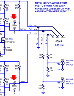
One more point ... your circuit diagram stops short just at the loudspeaker connection. Does the amp have an inductor/resistor network on the output? I note it does have the RC network (many call "Zobel" but as far as I know, a Zobel was designed to keep a constant impedance for a given reactance. Mostly, the RC's on the output are only needed to provide a load at high frequencies where open circuits might cause the open loop gain to go high and upset the phase margin (i.e. cause osciilation).
Since then I've only ever used standard computer grade power types, which are designed for high frequency operation. With low ESR and ESL they seem to be about the best, though I've not seen any recent distortion measurements.
Thanks to computers, there are a lot of compact, high performance electrolytic capacitors are available at a reasonable price. I've used them in line level power supplies and other audio applications. I have a single supply headphone amplifier with 4700 uF output capacitors that provides excellent performance. I didn't do any measurements to verify performance, but in reality audio frequencies aren't a big deal for even run of the mill electrolytic capacitors.
One more point ... your circuit diagram stops short just at the loudspeaker connection. Does the amp have an inductor/resistor network on the output? I note it does have the RC network (many call "Zobel" but as far as I know, a Zobel was designed to keep a constant impedance for a given reactance. Mostly, the RC's on the output are only needed to provide a load at high frequencies where open circuits might cause the open loop gain to go high and upset the phase margin (i.e. cause osciilation).
None of the LJM boards came with that, but I plan to add it.
I might just make it part of the lead between the board and the speaker protection board using a 3W metal film inside the inductor coils.
I tend to prefer to purchase metal film but I don't know if that is the best choice for these low resistance higher power resistors.
In general, the lower the value of resistance, the lower its inductance. In audio circuits, it's the higher value resistors that can affect circuit operation because of rising impedance with frequency. Of course higher value resistors can introduce more noise too, and using low noise high stability resistors offers the most benefit in these types of applications.
- Home
- Amplifiers
- Solid State
- JLH 10 Watt class A amplifier