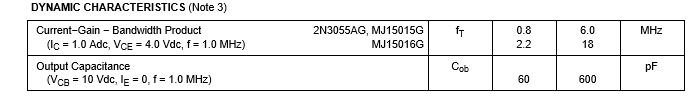
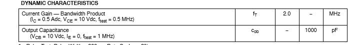
MJ15015/6 are the surprise, somewhat faster types among those venerable Motorola TO3 legacy, 1-4MHz Ft power transistors. Not the highest power, but plenty enough grunt for any home audio. If you want fast (Ft 30mhZ) and vastly better linearity, use the On semi plastic types in the MJL,MJW,NJW series - according to package style/power rating
At rather more expense, you may still find genuine TO3 MJ21193/4, which are also available in plastic as MJL21193/4. Still, these are about the best of the 4MHz power transistors anywhere.
At rather more expense, you may still find genuine TO3 MJ21193/4, which are also available in plastic as MJL21193/4. Still, these are about the best of the 4MHz power transistors anywhere.
You could go with a PNP output arrangement but you will need to find a PNP transistor as good as the choice for NPN in the split phase role.
BC327?
Last edited:
FWIW, its a waste of time looking for characteristics intended to improve class AB amps (i.e. high switching speed) when class A means no switching, just loafing along at 20kHz tops. Don't encourage instability by extending bandwidth without good reason. If someone has a good and relevant to JLH69 need for more than say, 500kHz bandwidth in class A, I'd be happy to listen though.
If you are driving low gain power transistors, I think you'll find a TO92 package driver gets hot, regardless of the type. It should work but use On semi -25 or -40 suffix types, not the generics available from many distributors now).
I use a TO-126 or TO-92L package drivers because I like touchable semis and some are just fine there. I can always tack on a heatsink if necessary.
I use a TO-126 or TO-92L package drivers because I like touchable semis and some are just fine there. I can always tack on a heatsink if necessary.
Am about to order the bit and pieces for my amp boards. I will do my testing with a variable voltage 10A lab power supply and then build my PSU once i'm happy everything is working.
I need to commit to a bipolar or single rail version. I'm not too worried about the presence of an output cap.
My transformer is a 300VA with dual 18VAC secondaries (not centre tapped). Any suggestions on which would best suit this transformer?
I need to commit to a bipolar or single rail version. I'm not too worried about the presence of an output cap.
My transformer is a 300VA with dual 18VAC secondaries (not centre tapped). Any suggestions on which would best suit this transformer?
That's what I think Ian. The BC337-40 might be 250 mW if ideal conditions. Luckily once running much is unchanging. That is not true of class AB. There the output transistors present a horrible load. For this reason alone class A might be better. I doubt it but possible. FETs present a very different load. The little FET design I show is quite powerful using a signal transistor as total driver and voltage amplifier. Even as shown the author claims JLH type performance. It might accept 1/4 amp standing current or even one amp.
Am about to order the bit and pieces for my amp boards. I will do my testing with a variable voltage 10A lab power supply and then build my PSU once i'm happy everything is working.
I need to commit to a bipolar or single rail version. I'm not too worried about the presence of an output cap.
My transformer is a 300VA with dual 18VAC secondaries (not centre tapped). Any suggestions on which would best suit this transformer?
I think you will have to experiment. You could try my single TIP3055 plus zener as you lose only about 1 volt. You could end up with 20V. You might have to set it up as if a 15 ohms load. At a guess you will get 6 watts which is a very loud amplifier compared with what people think. 50 watts is slightly more. The reason 50 watt amplifiers sound better often is that they are better. The watts are a bonus. I assume 0.9 amps. I trust the 3055 ( 2955 if PNP ).
Use one regulator and winding per amplifier.
I will look at a 1960s version as I think it should give you slightly more voltage. Could you say your home AC voltage as I can clone that. The maths is well known but easier just to test it. The 1960 version should give less diode noise.
There is an unusual way of getting more volts at low cost. A 100 VA 0-6 0-6 can be added as a boost transformer. Equally a buck transformer. The amperage identical. Thus you have 24 VAC as double or single windings. 6 VAC being as small as it usually gets. Two at 50VA 4.5 VAC might be possible. My 60 to 300 VAC PSU works this way.
You can get two sources up to 24V or one bipolar.
So either one power supply with 2 1996 version channels powered from it, or one power supply from the rectifier onwards for each 1969 channel?
Are there any real advantages to having separate supplies for each channel in a simple Class A design like this?
Am about to order the bit and pieces for my amp boards. I will do my testing with a variable voltage 10A lab power supply and then build my U once i'm happy everything is working.
I need to commit to a bipolar or single rail version. I'm not too worried about the presence of an output cap.
My transformer is a 300VA with dual 18VAC secondaries (not centre tapped). Any suggestions on which would best suit this transformer?
If you are happy with a possibly slightly reduced power output with a single rail and capacitor coupling to the load as in JLH1969 you could use each winding with separate bridge rectifier and supply capacitor per individual amplifier. I used the word possibly as your transformer has more than enough oomph and it might give a rectified voltage that is higher than what might be expected. I had a transformer custom made like yours for 22 volts in each winding. The target rectified figure was 27 Volts it was rated at 300 v.a. and made in Australia - I don't remember the manufacturer but they made it not to fall short and with with a load drawing 4 A the rectified supply rails were +/- 30 Volts
Last edited:
I should have said. Don't use the plus minus PSU. It sort of guarantees you will damage your speakers. The output capacitor is not easy detected by ear. I have tested this. Like testing wines from the same year neighbouring slopes it might be imagination that the difference can be detected. Whereas cheap Panasonic FC capacitors inside the amplifier do give a more transparent sound. Your output capacitor should be better than two amps ripple current which should be any really. The output capacitor is the best electronic DC protection known on planet Earth. I can almost say for certain you will need it. I destroyed two pairs of high grade headphones using plus minus PSUs. As I didn't want to build a new design I added nonpolar ouyput capacitors.
Thus 1969 version.
It's said some wine experts didn't know red from white wine blindfolded. That is more complex than people think. All the same it shows some of this is scientifically doubtful. Blindfolded people lose confidence and shift to different parts of the brain. AB compare with friends where really it's AA. Most hear indentical second A as brighter and more detailed. Nothing weird about it. The brain learns.
One of the interesting if not great improvements to stereo amps is the enhanced stereo image possible with "dual mono" construction. Normally, this means using two transformers, power supplies and the common ground connections only meet at the single chassis ground/protective earth connection.
This means your dual windings can offer an advantage as well as doubling up for either type of overall design. Stereo isn't quite as pronounced with the one transformer/2 separate windings and single rail but it should still result in a better stereo image if you "dual-mono" it. That's my experience, at least
Incidentally, AKSA's amplifier designs are examples of the full dual mono transformer and power supply approach that many audiophile constructors have followed religiously for decades.
If you let me know the house voltage. I will build this. Use standard diodes at least at first.
The stereo thing is a bit misleading. It usually is just a better PSU with less problems. > 20 dB is stereo as our head ruins it.
As someone from the otherside of this industry I have to go along with all the hype. Good engineering is all that matters.
I was told once that Rod Elliot of ESP is just for beginers. He knows far more than me. He is like a doctor who says take an asperin knowing it to be a super drug. To other doctors that's a bad doctor as it destroys the illusion. To me it doesn't.
- Home
- Amplifiers
- Solid State
- JLH 10 Watt class A amplifier