If I choose to make that circuit I will follow your advice and replace with zeners for over voltage protection,.
With 500ma bias on each output device my ripple is 80-90 Mv, I'm not happy with those numbers, those figures are from two standard bridge rectifiers with 2 470000uf capacitors, tried some different values snubbers, it seemed to have negative effect (might work better with quasi modo bell ringer) the I tried some faster mur3020 diodes, that resulted in 90Mv ripple, could you smoothen that sharp 100hz triangle after rectifier with two low ohm power resistors?. Or is it just more heat?
Rallyfinnen I think those diodes might just work, or one could make a DC sensing circuit, when dc is above 20Mv signal output is passed through a capacitor like the old jlh.
Hi Amplitude,
well done on getting your JLH up and running, It is very rewarding when you hear that first song through something that you have hand built.
On the subject of the capacitance multiplier, if you look at Rod Elliot's version he uses 2 low-pass filters in series when providing the drive to the controlling transistor (Rod uses a Darlington pair). This reduces the ripple even further and is well worth the extra resistor and capacitor.
You can find the project here:
Capacitance Multiplier Power Supply Filter
Happy listening
Mike
Rallyfinnen I think those diodes might just work, or one could make a DC sensing circuit, when dc is above 20Mv signal output is passed through a capacitor like the old jlh.
Or just disconnect the speakers, forcing you to wait for sound until it has heated up!
Actually, some standard DC protection board might work, just bypassing the relay contacts with capacitors.
Let's not hope your jlh has gigantic heatsinking , but yes there are dozens of dc protections out there.
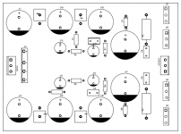
By the way heres a initial layout for a capacitance multiplier.
Its recommended to use tip35/36, but I'm all out, instead I have 30 mjl1302a mjl3281, is there a reason why I couldn't use those? As I understand high hfe is preferred, and those top the tips.
If power is a problem two could parallel with ballast resistors
, but yes there are dozens of dc protections out there.By the way heres a initial layout for a capacitance multiplier.
Its recommended to use tip35/36, but I'm all out, instead I have 30 mjl1302a mjl3281, is there a reason why I couldn't use those? As I understand high hfe is preferred, and those top the tips
.If power is a problem two could parallel with ballast resistors
Attachments
JLH like 24V SMPS as there will be no 50 Hz ripple.
My JLH 1969 boards went to a friend that built them in a casing with 2 pieces Murr 25V 5A SMPS that I recycled with Panasonic FC/FM capacitors. The idea of having heavy toroids and large caps rewarded with mechanical and electric hum dit not appeal. The SMPS just deliver and the amplifier is smaller, lighter and it generates less heat.
It is a good marriage between old and newer technology.
Last edited:
You don’t hear that unlike 50/100 Hz
Seriously, that crossed my mind too but the industrial SMPS are quite good. If one really wants ultra clean power one can consider a pi filter. It is easier to filter RF out than 50/100 Hz with a class A amplifier. The ripple class A amps cause on rectifier/cap PSU’s is detectable by ear so the worst.
Seriously, that crossed my mind too but the industrial SMPS are quite good. If one really wants ultra clean power one can consider a pi filter. It is easier to filter RF out than 50/100 Hz with a class A amplifier. The ripple class A amps cause on rectifier/cap PSU’s is detectable by ear so the worst.
Last edited:
TThe MURR are OK except older series that have bad caps. The DIN rail mount versions are easier to use. The open frame types connect your chassis and possibly audio GND to PE. Casing and primary side of SMPS connected to PE is fine (way better filtering too!!!) but audio GND should float IMHO.
* when the SMPS has PE connection one MUST use it. For safety and for filtering.
* when the SMPS has PE connection one MUST use it. For safety and for filtering.
Last edited:
As best I know 100 mV offset is harmless. It's even possible that a deliberately engineered larger inward offset could improve the sound. As a JLH is unlikely to explore the limits of the speaker one can play. I suspect inwards offset could reduce second harmonic distortion slightly. -ve offset if the speaker moves forward with +ve.
I would guess up to 1/2 watt it's ok. Remember the speaker cools itself at modest levels if the magnet or dust cap is ventilated. That also reduces distortion. The second harmonic I refer to is speaker distortion. Most speakers will be noticeably different if second harmonic reduced. Faster sounding and often better if so.
I had a little Russian TV called Rigonda. It had a SE class A amplifier with no output capacitor. The DC offset was considerable. The speakers engineered to centre! I without thinking connected my perhaps Whafedale Lintons to the TV. My brother was horrified. It worked for weeks quite alright. The more remarkable thing was he was 10 and already knew about SE class A.
Simon died a few years ago from a mystery virus rather like now. Such a shame he never joined DIY Audio. He made complicated things easier to understand. I have all his test gear.
Hello all,
My heatsinks that were just bare Aluminium.
I bought some heat resistant spray paint, 3 coats and baked in the oven for 1 hour at Regulo 5 (190.C)
I've been in many a powder coating works and the smell was just the same, brought back some memories.
Cheers
My heatsinks that were just bare Aluminium.
I bought some heat resistant spray paint, 3 coats and baked in the oven for 1 hour at Regulo 5 (190.C)
An externally hosted image should be here but it was not working when we last tested it.
I've been in many a powder coating works and the smell was just the same, brought back some memories.
Cheers
Member
Joined 2009
Paid Member
you may not need to use a capacitance multiplier on the output power stage; in my version of this amplifier of which there is a thread somewhere called TGM10 I simulated the amplifier with a capacitance multiplier only on the front end and it gave all the benefit for PSSR whilst leaving the power stage free to do its thing
- Home
- Amplifiers
- Solid State
- JLH 10 Watt class A amplifier