Why not use two polarized caps back to back instead..?thoglette: I did let it settle before about 3s before starting the sine. It seems to be pretty stable at that point. I have not simulated clipping more than by mistake..
Loudthud: I'm not sure I understand the question? I have not simulated the Zero zone PNP at all.. I only modified it to floating ground, and adjusted some resistor values in the current source to reduce distortion, and added some HF filters (RC)
I posted the schematic for it somewhere in this thread.
I've been looking for bipolar electrolytics in the +1mF range for the feedback cap, but I have not found any good candidates in stock in Sweden or Europe. A lot in the US though.. but shipping from outside EU makes it expensive. They need to be pretty small to fit the PCB etc.
Suggestions welcome.
Loudthud: I'm not sure I understand the question? I have not simulated the Zero zone PNP at all.. I only modified it to floating ground, and adjusted some resistor values in the current source to reduce distortion, and added some HF filters (RC)... I posted the schematic for it somewhere in this thread.
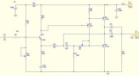
Sorry, I thought you had simulated the PNP. Attached below is the schematic I found. Is this the right one ? It's basically just the JLH69 with reverse polarity transistors. I found it by clicking on the paper clip you see in the thread listing in the Solid State forum that brings up a listing of all the attachments in the thread.
When you say floating ground, do you mean converting to dual rail power supplies like the JLH 2003 update version ?
Attachments
Sorry, I thought you had simulated the PNP. Attached below is the schematic I found. Is this the right one ? It's basically just the JLH69 with reverse polarity transistors. I found it by clicking on the paper clip you see in the thread listing in the Solid State forum that brings up a listing of all the attachments in the thread.
When you say floating ground, do you mean converting to dual rail power supplies like the JLH 2003 update version ?
That's the one. The floating (virtual) ground is created with capacitors, see the 'sublimed jlh' thread for more info. The zerozone version with rectifier and capacitors was ideal for this, using all the caps for the floating ground, and a switched psu for supply. I have some pictures of the modified board here in the thread too. I changed R25 to 200 Ohm, this was a good value for low distortion with 19,5V supply and just over 1A Iq.
@Rallyfinnen, I think this is the thread: sublimed JLH1969
Very interesting, I'm reading it now. Thanks for the reference.
Very interesting, I'm reading it now. Thanks for the reference.
I have been thinking. JLH talks briefly about making the bottom power transistor a Darlington and how it has lower distortion. He didn't say modifations required. Being that this is a class A design it probably will work with a primitive Darlington. Collector to collector, emitter tr1 to base tr2. It shouldn't need additional heatsinking. BD139 if original design. If it works it gives more freedom when choosing the driver, BD139 again perhaps? I would recommend modern output transistors due to higher current gain. Oscilloscope would be required.
Hi Nigel and Ralleyfinen,
Quite a few months ago I experimented using Darlingtons in a JLH (the latter version from Geoff Moss) we decided to put it in its own thread
JLH-D16
It didn't go further than my showing some work I did, and I still use my Geoff Moss JLH as, to me, it sounded better overall, although I updated it to using 4 output pairs. Note that when using multiple output pairs, the higher hfe devices should still go in the lower position for the lowest distortion.
I also played around with using a Sziklai pair as the voltage driver/phase splitter and the results are there as well.
Regards
Mike
Member
Joined 2009
Paid Member
I tried a feedback pair driver on another project. It was hard to say why but it wasn't as good as I hoped. The sound was I guess less detailed. Phono preamps sometimes used a variation of feedback pair with gain. I built a version with no equalisation recently. It was ok but nothing special. The gain was about three and distortion about 0.03%. Perhaps the curve cancellation of npn/pnp gave unfortunate harmonics. It was bland and a bass light despite having generous coupling capacitors. That's quite a good point. The NAD 3020 has very low grade capacitors and yet sounds good. Some circuits that should sound good don't. If you study the NAD it's not the usual design of let's say a Denon PMA 250. Some pundits say this and that about it. All I can say is like the JLH it's designed by someone in love with design. For example a long tail pair is not used in the power amp nor the JLH. However one is used in the preamp. That clearly shows an understanding of where best to use it.
Technically we could get a little bit more performance from the JLH by tweaking the gain and possibly feeding signal into the feedback capacitor. If using a nonpolar capacitor sometimes increasing the gain sounds better despite the distortion rising. I found that if third harmonic is below 0.03% it should be OK. A little more gain is useful sometimes.
The other suggestion of signal to the feedback capacitor might require decreasing the gain so as to make the resistor easier to drive. Op amps can easily give 5 Vrms so that is an option. A preamp with buffer stage is an idea. It will drive headphones also.
The reason that the feedback capacitor signal input is good is that feedback from the speaker terminal is summed with the input signal directly. The signal is then amplified via the emitter as a common base amplifier that is as superior signal path if enough current is available to drive it. Although into the base is ok as is standard the simple summing is technically better due to minimum time delay. I bet that the gain is a big factor. It's the resistor associated with the feedback capacitor you tweek.
I will have to trace out the JLH as I am working from memory here. A common base amplifier has an in phase input. However the signal has to be out of phase to ground to set gain. If someone gets there first I'm happy.
Last edited:
The 2nd harmonic went from abt -80 to -60dB, and the falling spectrum of higher harmonics was raised with it. I don't plan to dig in to it more at the moment, but it was an easy test to just solder it in and measure.
Yes, quality varies with the kits, but I would say the ones I tried have at least worked as expected 'out of the box', no oscillations etc. The worst ones were probably the white boards with really poor performance of the 3055's supplied with the kit. Probably fakes.
Yes, quality varies with the kits, but I would say the ones I tried have at least worked as expected 'out of the box', no oscillations etc. The worst ones were probably the white boards with really poor performance of the 3055's supplied with the kit. Probably fakes.
It's a great shame Andrew T isn't with us anymore. I would have asked him to calculate the current used throughout the amplifier. It always seems impossible to me that the driver transistor can ask 2 amps to pump the speakers via the output transistors.. Has anyone looked at this?
The driver transistor is doing quite a few jobs. When I build my next version I am going to measure the input and outputs. I am not quite sure what I will see. The input might be quite distorted due to it being a current to voltage converter. Many say that's irrelevant. Perhaps it is a source of IM distortion. The very high base setting resistor 8k2 suggests this. Back in time series resistor was added which also could act as filtering, typical valve tweak. Richard Hay of Nytech made beautiful sounding amplifiers. He said not measuring things like this when other people is why his amplifiers sounded so good. They also were deceptively simple like JLH.
The driver transistor is doing quite a few jobs. When I build my next version I am going to measure the input and outputs. I am not quite sure what I will see. The input might be quite distorted due to it being a current to voltage converter. Many say that's irrelevant. Perhaps it is a source of IM distortion. The very high base setting resistor 8k2 suggests this. Back in time series resistor was added which also could act as filtering, typical valve tweak. Richard Hay of Nytech made beautiful sounding amplifiers. He said not measuring things like this when other people is why his amplifiers sounded so good. They also were deceptively simple like JLH.
I did a quick test with a Sanken MN2488 in the lower position and a C5242 in the upper. Distortion got significantly worse, and I also got oscillation. To clarify, this was on a 'standard' 69 JLH with single supply and output cap.
It does have remarkable specs. Current gain can be 50 000 ( at least 3000 ) and only 95pF capacitance with 55 MHz if the Japanese sheet was understood. Although not a serious Idea a BU508 BD139 could be better. The 508 is a TV device gain of 5 and reasonably fast. I strongly suspect an MJ15015 ( 3055 ) and verified nos BD139 could be good. I am 90% certain only gain matched to stability matters. I suspect new BD139/140 could be MJ340/350, who knows. The originals were very fast.
Let me prove something alone those lines. My brother built me a valve amplifier using a Vox AC 30 output transformer. We knew for a fact it rolled off at 7.5 kHz. It sounded wonderful and bright in a good way. Just enough negative feedback was added to make it measures well. The results were awful. We found out why. It was feeback induced. The good news is transistor amplifiers love feedback due to being mostly current amplifiers. The doubt is the driver. The point is something that on paper is right isn't always best sounding. That amplifier was one of the best I ever heard and simple. 2 x EL34 pp triode. ECC 82 in long tail pair no loop feedback. About 14 watts in fixed bias. I would guess a long tail pair of ECC82 would have a gain of about 7 and the EL34 needs about 28V RMS so would have required more than the usual preamp to drive it. An additional ECC83 and 20dB feedback was a typical 1960s design.The simple one better. Despite 1% thd it was one of the most life-like sounds.
Hmm..
the one position I have not tried a S-pair is the output stage of a Geoff Moss JLH. Sounds like a project for the up and coming summer evenings, although I might try it out in LTSpice first having now got a rudimentary handle on the software.
Rod Elliott is also a fan of the S-pair in an output stage, but he always uses complementary devices (IIRC) and has to slug the base-collector on the the lower device.
regards
Mike
Last edited:
I would greatly appreciate that. Keep us posted
I moved into my new house is September. I have just got my Garrard 401 Hadcock GH220 Denon DL 110 plus weight working today. The arm recently bought and required repairs. The sound is what I hoped and incentive to get on building some new gear. The 401 sounds more like a good tape recorder like Revox.
I moved into my new house is September. I have just got my Garrard 401 Hadcock GH220 Denon DL 110 plus weight working today. The arm recently bought and required repairs. The sound is what I hoped and incentive to get on building some new gear. The 401 sounds more like a good tape recorder like Revox.
Member
Joined 2009
Paid Member
I actually did one more test on the same 69 boards today, after changing back from the lower darlington to double C5242 outputs. I replaced the 'A06' driver/splitter with a BC337-25. In general measurements were about the same as with the A06, possibly a little lower 'grass' around 13+14kHz when measuring IMD. The 1kHz component of the IMD measurement is still a little bit high for my liking on this amp.
Last edited:
I have just got my Garrard 401 Hadcock GH220 Denon DL 110 plus weight working today. The arm recently bought and required repairs. The sound is what I hoped and incentive to get on building some new gear. The 401 sounds more like a good tape recorder like Revox.
Hi again Nigel,
you mentioned your Garrard 401 - I also have one of these beasties coupled with a SME 9 inch arm and a Ortofon Black cartridge

However, the rumble has become apparent after lack of use for a year or so. I have 'anointed' the motor and idler bearings with the appropriate oil (fine sowing machine oil from my wife's collection, as specified in the manual) and cleaned the inside rim of the platter. Have you had cause to do more than this?
Kind regards
Mike
Last edited:
- Home
- Amplifiers
- Solid State
- JLH 10 Watt class A amplifier