Thanks for the feedback, I don't think TTC5200 is the best option with this amp.
Of course, it is good for testing, I will use some slower transistors like MJ11003, MJ802 or if you go with a flat case transistor MJL21194 etc for a start. Maybe at +/-18V, 1 pair sounds better because of the higher bias per device.
At least we know the amp started up and works.
Of course, it is good for testing, I will use some slower transistors like MJ11003, MJ802 or if you go with a flat case transistor MJL21194 etc for a start. Maybe at +/-18V, 1 pair sounds better because of the higher bias per device.
At least we know the amp started up and works.
Thanks thimios for sharing. And congrats on getting it working.
Yes Gabor has boards too and building it (hopefully) and he is the one who make me design this pcb .
.
Regarding ttc5200, it was mentioned in the original documentation of jlh2003 update (the link I shared some time earlier).
Regards
Prasi
Yes Gabor has boards too and building it (hopefully) and he is the one who make me design this pcb
.Regarding ttc5200, it was mentioned in the original documentation of jlh2003 update (the link I shared some time earlier).
Regards
Prasi
Last edited:
Thanks thimios for sharing. And congrats on getting it working.
Yes Gabor has boards too and building it (hopefully) and he is the one who make me design this pcb
Regards
Prasi
Then his opinion is more important
I bought it and I got mad with the seller.
it's just a P version of a jlh69 with mosfet output and all that without any amenagement.
I have never assembled, I do not want to burn everything.
I have not tested the MOS but I have a big doubt when their origin ...
for information, it's the same seller who stole a schema to destroy X and put it on aliexpress and ebay ...
So, I'm not buying anything from him
I have ordered it, out of curiosity...I know that those sellers are scumbags stealing designs all over, but 1969 circuit is free to anybody.
I have the same question.Sorry adason, but I don't understand why so many guys get deceived by Chinese thugs. China/aliexpress/ alibaba is all about stealing designs and making duplicates that seem to work...may not be reliably..
When there are so many designs here..
Regards
Rossi
Personally i can't listen something wrong using TTC5200....
Are you test personally or just read something?
2MHz output transistors are good enough. These have less bandwidth than the transistors in the preceding stages and the gain of the system has to reduce to one (unity) before phase gets to - 180 degrees.
If you use a 30 MHz device as a replacement you will reduce the phase margin and make your amplifier less stable.
JLH described the operation of the 1969 circuit in his book "Valve and Transistor Amplifiers" (page 155) thus - "Because the transition frequency of the output transistors is of the order of 4MHz, whereas those of Q3 and Q4 are in the 400MHz range, the circuit has an in-built dominant lag in its loop NFB characteristics. This ensures that the loop gain has fallen below unity before the loop phase angle reaches 180 degrees. No additional HF compensation networks are therefore necessary to ensure complete stability, even with reactive loads."
In nature the rate of increase in phase is greater than the decline in frequency. Phase starts to change a decade in advance of frequency - this applies if frequency is increased or decreased so you are dealing with quite a mercurial property and not a rule of thumb so you have to know what you are doing.
The simplest advice to avoid trouble is to stick to the script.
Last edited:
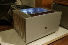
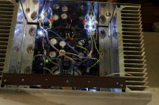
Hello potepuh,
That's a very nice build
So the design jlh2003 works with both to-3, to-264 both on same pcb...
Very very flexible pcb design
Someone made wonderful PC boards. Thank you prasi!
I just started stuffing the PC boards today, it will take some time, I miss some key items. L bracket for metal can transistors.
Found some on Ebay but is horrible expensive because of the shipping cost. 1pc 6061 T6 Aluminum Structural Angle 50mm*50mm*500mm,Thickness=5mm #EB45 | eBay
I did check a couple hardware store they only have 3mm type. That is not good (thick) enough.
I was interested in this amp since the original was built and published.
For some reason, the mentioned transistors are preferred.
I read the MJ15003 better than the MJ15023 from ON Semi.
Pardon me if I posted the wrong number like NPN VS PNP.
MJ802 is a great transistor for this amp also.
Please follow the PS table V/bias setting as close as possible.
If you use only 18V rail voltage is 1 pair power transistors preferred.
Yes, one more great amp built, thanks for the feedback.
It is almost certain that modern 2N3773's are built in an epibase or similar line and have higher fT than the originals, but the D/S still says 200kHz (min).
It is not too difficult to measure the fhfe - set the transistor into Class A at whatever (e.g. 1A) with a low resistance load (e.g. 0.1 ohm) and feed an AC signal into the base from a low impedance source (or, if you want to check the effects of a higher resistance, include a suitable load resistor in series).
I usually use a dual PSU with a large emitter resistor (in watts) e.g. 10 ohm 15W with a large cap to ground to set the current, and a base bias through a pot of about 1k, depending on what base impedance you would accept.
I'l have to check whether I have any new 3773's and measure later if so.
Last edited:
Thanks for replying.It is almost certain that modern 2N3773's are built in an epibase or similar line and have higher fT than the originals, but the D/S still says 200kHz (min).
It is not too difficult to measure the fhfe - set the transistor into Class A at whatever (e.g. 1A) with a low resistance load (e.g. 0.1 ohm) and feed an AC signal into the base from a low impedance source (or, if you want to check the effects of a higher resistance, include a suitable load resistor in series).
I usually use a dual PSU with a large emitter resistor (in watts) e.g. 10 ohm 15W with a large cap to ground to set the current, and a base bias through a pot of about 1k, depending on what base impedance you would accept.
I'l have to check whether I have any new 3773's and measure later if so.
I have some old (salvaged from an old amplifier) 2N3773.
I would be happy if you can draw a schematic.
This is slightly more complicated than I might have implied. The transistor under test is powered from a dual supply but the base current is provided by a constant current source, which is modulatable using a signal generator. In the circuit diagram a PNP transistor is used which has a high fT and is run in effectively common base mode if the impedance of the sig.gen is low, so this will work for most power transistors of the 1-10MHz range. MIght work with a better CCS for higher frequency transistors.
All resistors in the bias chain may need optimising for the base current needed. The DC current is set by R1 and R2. The modulating signal is set by the amplitude of the sig. gen but I recommend limiting this to about 10% of the DC value to keep things reasonably linear.
The output is taken from a 0.1 ohm resistor (non-inductive) but will be in the order of 10mV for a 1 A current in the transistor under test. If you need a larger voltage, you can increase this resistor, but above 1 ohm might start introducing Miller effects from the Cjc.
I have found this rough and ready check of fhfe and in some cases fT works reasonably well.
(fhfe is likely to be in the range 10-100kHz except for old slow 3772/3773 which may be as low as 5kHz)
How old are your 3773's. If pre-78 they may be slow ones and I would not advise using them in a JLH.
Attachments
Last edited:
The Motorola ones with a manufacture date post 1984 will be epitaxial-base types according the Selector Guide and Catalogue of that year which lists these as 4MHz types. I had an early Power Devices Handbook which said as much but I don't have this any more.
I built the JLH 75 Watt amplifier published in Hi-Fi News some time during the 1980's using these devices. These were in non-magnetic alloy with a low can profile and a dull finish - I had checked out the specs before buying these particular versions. The types made by RCA were hometaxial-base 200k spec devices.
I built the JLH 75 Watt amplifier published in Hi-Fi News some time during the 1980's using these devices. These were in non-magnetic alloy with a low can profile and a dull finish - I had checked out the specs before buying these particular versions. The types made by RCA were hometaxial-base 200k spec devices.
On second thoughts, I don't think my emitter resistor and decoupling capacitor are necessary in the fhfe measurement circuit. Since the base current can be set independently anyway, and Ic measured by the voltage across the collector load resistor, the circuit should work just as well with grounded emitter, but be careful that the collector current is not excessive (maximum R2 first).
And a reasonable heatsink is needed, not necesarily for continuous power if the measurement is made quickly,
And a reasonable heatsink is needed, not necesarily for continuous power if the measurement is made quickly,
- Home
- Amplifiers
- Solid State
- JLH 10 Watt class A amplifier