They are first class speakers aimed at a market which will have changed by now due to the better sounds of today. In the past we were told CD was correct and if we didn't like it that was due to our ears. Gradually CD improved. With some thought the speakers can be redesigned a bit. Active comes to mind. Passive design is hard. Moving the original design a bit would be the easier route. Try caps a little smaller or larger. Then better quality. Often better means brighter and you might like " worse " more. Royd speakers had seemingly awful NP electrolytic caps. A high grade sounded worse as Joe designed for that capacitor. It was subtle, the better one was a bit harsh.


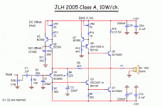
+15v/0/-15v
I think you need a secondair with a midpoint
Yes that is what i mean
+15v/0/-15v.
Member
Joined 2009
Paid Member
If you build the chassis and power supply well - then leave flexibility regarding the amplifier. If you decide the JLH is not for you, then you can swap in a different amplifier, perhaps a Nelson Pass design, and continue to get value from your investment of time and effort into the chassis and power supply.Time will tell if I like the JLH or not I guess - worst case, it'll be a learning experience. Haven't build anything from scratch, more or less, since my days as an apprentice which ended back in the mid 90's.
Power supply +/-15v
500mA idle current
-15v in speaker out.
Something is wrong here.
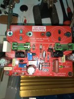
Prasi, please can you post schematic diagram that match this pcb?
+15v/0/-15v
I think you need a secondair with a midpoint
Yes that is what i mean
+15v/0/-15v.
As I read it, you have
V+ / spk / V-
Pretty sure V+ and V- goes directly into the fuses next to them (left and right respectively) and the common speaker rail to the SPK pin in the middle - with a common ground at the front of the board.
So I think it's correct (if I am at least) ( :
I have lived near Oxford for 62 years. A bit of a love hate thing. Friends agree we might only know 1/3 of the city and think we know it all. I recently read about the old railway gas and electricty companies. Oxford was an industrial city with a university lost inside it. Over the years since 1969 the industrial part inside the city has been rubbed out and made a little more beautiful. I think I liked the old one better, it was very grubby.
I just reread the JLH again. Born as Oxford started to become Disney Land. I was in Paris in 1967. The guide said look carefully as one world ends and another begins. I did. 1920's style buses in common use and Citroen DS, Wooden rail Metro in baby blue and cream.
http://www.keith-snook.info/wireles...ss-World-1969/Simple Class A Amplifier - .pdf
I was looking for loop gain which is a very low 600 or 55 dB. Of this 34 dB is used as feedback resulting in 0.16 ohms output impedance or damping factor of 51 at 8 ohms ( excellent really ). Distortion is 0.05% of which most is second harmonic. This implies about 2.5% open loop, I have been told it's higher.
What JLH never says is why the amplifier is so simple. There is every reason why he would strongly question his own wisdom here. It's always said transistors were more expensive then against wages. The hardware would then as now would be the bigger cost. I can only think like me JLH thought that every extra transistor colours the sound. JLH says the laboratory can not duplicate everything that happens. Like Oxford do I know 1/3 of how this really works?
JLH
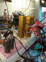
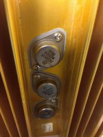
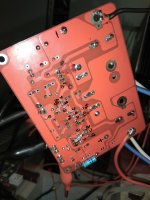
Some photos from first test after debugging.
Last photo the solder side after debugging still dirty but playing nice!
Some photos from first test after debugging.
Last photo the solder side after debugging still dirty but playing nice!
Attachments
Last edited:
Member
Joined 2009
Paid Member
I have lived near Oxford for 62 years. A bit of a love hate thing. Friends agree we might only know 1/3 of the city and think we know it all. I recently read about the old railway gas and electricty companies. Oxford was an industrial city with a university lost inside it. Over the years since 1969 the industrial part inside the city has been rubbed out and made a little more beautiful. I think I liked the old one better, it was very grubby.
I was born there (known locally as the Nuffield I think), studied and lived there. I like it cleaner to be honest, but it's too crowded now, I hate the crowds except early morning 1st May

Last edited:
You must like me have been born at the Churchill the old US hospital.
My Saga of oscillators goes on and I think reaches an end. I did not show the full circuit as it's ESP's copywrite. It's the lamp state variable filter type.
ESP - Sinewaves
I have added a 3 rd harmonic null as shown in the Analogue Cookbook 1992. Rods circuit is better than theirs. I had to use 27K for R3 and not 56K. The null transforms it to a very good device. At 1kHz ( 10 nF 16 K ) it's even better. The null reduces the output from 2.5 Vrms down to 2Vrms. If it doesn't it's not right. 10 kHz shown. 3 rd harmonic off the scale.
The Elektor design is better at 1kHz. It is very hard to tune to other frequencies.
https://www.elektormagazine.com/files/attachment/326
Thanks Prasi i hope all are under control now.
Possibly this is what you has seen.
I will post schematic with measurments as built later.
Hello Thimios ,
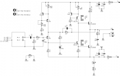
yes, the schematic is as per The Class-A Amplifier Site - JLH Class-A Update
figure 2.
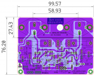
My sch and layout is attached here.
regards
Prasi
Attachments
Yes i see,maybe i had the problem due to C grade (bc560c) transistors?Hello Thimios ,
yes, the schematic is as per The Class-A Amplifier Site - JLH Class-A Update
figure 2.
My sch and layout is attached here.
regards
Prasi
btw what is the max recommended power supply?
- Home
- Amplifiers
- Solid State
- JLH 10 Watt class A amplifier