BTW other Nigel I was told not to do drawings like I do in 1972. That's about before CMOS was for sale. I was also told not to use amplified zener diodes. I still do that. Bootstrapping was OK. In fact bootstrapping is still widely used and often not understood as being that. Bootstrapping is as close to being a miracle as it is possible to get.
BTW2. You could even run the tail from a 9 V battery , As the JLH has a bit of second harmonic 9V would not be awful. If using 2SA970 the tail can be at 80V if you like. You would use 530K if so. That will make it more linear without the need for a current source. The hybrid when perfected is easy to improve.
The Naim ratios are 1K 22K, The Tr3 emitter resistor is the JLH value. If you did use a 9 V battery there would be no capacitor to the tail resistor. It would be 56 K tail resistor value. It's something you can play with and think about.c18V would be 110K, With a 45 V transistor you can risk 30V ( 43.5 V total ). Naim did this. The battery -ve would be to the centre voltage rail. This is easier with the DC coupled type where centre is 0V.
The bootstrap works well in the original JLH because it has the ability to raise the positive going output drive stage above the Vcc rail, and although there is some non-linearity in the lower bootstrap resistor due to the exponential Vbe of the op transistor (which is partially linearised at higher currents due to series resistances) the omission of an emitter resistor does not add a class B current asymmetry. As a result of being able to drive above Vcc, it has the best efficiency (lowest voltage burden). A CCS would add at least a volt or so to the voltage burden and need a higher supply to maintain full o/p.
I think many suggest these types of bootstrap current sources are a poor substitute for the 2 diode one transistor modern ones. Having measured then side by side they both work very well. I built one where the bootstrapping RMS voltage was 15 Vrms and the stage 28 Vrms. It still worked very well. That was what I could do there and was delighted with what I got.
The LTP tail circuit allows as many " What if I did this " experiments as you could want. The simplicity of an op amp for that is exactly what it is. 90% ideas no matter how daft will work well enough to say " that's daft ". The machine will live another day. The JLH can not do that. Nearly everything you try makes another part change.That'as fine if you really understand how it works. Even then it's easy to make mistakes. Nearly switching off LTP No 2 ( 180 K ) gives a spectrum more like one transistor. If it can work with this low current I don't know. The speaker output voltage will say plenty.
The situation I understand to have happened is the Naim ( NAP200 )in 1971 had started life to replace the Quad 303. The 405 was Peter Walkers baby so the ??? never was produced. Julian Vereker was advised by Bob Stuart to improve a Sinclair Z30 to learn from with big PSU. Bob joked to me he never exspected Julian to market that exact idea. Bob is being a bit naughty to say that as whilst the A&R A60 is just that the Naim isn't. The Nain is not much like the RCA people talk about. Knowing RCA one example might be like it I haven't seen ( Harmon Kardon used similar ). More likely the LM741 inspired them all. Despite being a low grade device now the 741 was the blueprint for modern devices. My guess is Alan Mornington West helped Julian make a sound like the 303 with more dynamic power. I had a very brief email conversation with Alan. He really did not want to know. Sad as he is a hero just like JLH. He talks like he was on the substitute bench when he was really Ronaldo.
Hello.Hello
Messing with ft or beta (Hfe) will change the behaviour of the amplifier, usually not in a good way
Do read through the whole of the thread as this has been discussed more than once.
A quick summary (I think) to save you reading 5000 posts...
High gain transistors are not a problem. JLH use devices with high and low gain. But you need to adjust the driver current to get the right quiescent current in the output transistors.
High ft transistors could be. I recommend adding small compensation capacitors as that worked with MJL3281A's. People have reported mixed results without, as I found.
And there's the rub. Add gain and/or Fte and your Bode plot's buggered.High gain should be good and should be better. It might be stability is reduced and needs some mesurement.
There's half a dozen examples in the thread of people successfully swapping transistors and they've all (IIRC) had to tweak the gain or phase response to bring the design back to the stable place where JLH left it.
That's true and that's the freadom one might want. Both Rod Elliot and Douglas Self make a point about this. They both think an external capacitance is likely to be a better solution when the so called VAS. Self thinks the internal capacitance a poor substitute for a NPO/GOG capacitor. Elliot says the supposed stability of these 1960's amps is not due to the singleton input, it's a high capacitance VAS. My tests seem to go with his. All the same a longtail pair must be marginally worse.
When I used BC327/337-40 and Indian 2N3055E ( my guess, not H ) I had to fit 33 pF to the driver splitter 337-40. Before I did there was the beginings of some output at 500 kHz to 2 MHz, about 3 dB above the noise floor. I suspect 16pF would have been enough. The distortion at 20 kHz was about 7dB better than many get. It reduced to 0.03% at near full power. It was a quick fix. I suspect a better one exists not using this transistor position. 327/337 seems to me the better choices we now can get. They are more unlikely to be fakes. The 337 never got warm at 27VDC rail. I would imagine the gain of the 2N3055 matters greatly. These ones seemed to be > 100 at 1 amp meausered.
When I used BC327/337-40 and Indian 2N3055E ( my guess, not H ) I had to fit 33 pF to the driver splitter 337-40. Before I did there was the beginings of some output at 500 kHz to 2 MHz, about 3 dB above the noise floor. I suspect 16pF would have been enough. The distortion at 20 kHz was about 7dB better than many get. It reduced to 0.03% at near full power. It was a quick fix. I suspect a better one exists not using this transistor position. 327/337 seems to me the better choices we now can get. They are more unlikely to be fakes. The 337 never got warm at 27VDC rail. I would imagine the gain of the 2N3055 matters greatly. These ones seemed to be > 100 at 1 amp meausered.

I had to build this Elektor design to know how to adjust my JLH. I used the most typical 28V 40 mA lamp ( aircraft? ) . I have no idea if optimum. Notice I am at my limit of measurement at the first integrator. -96 dB is stated in the text. My measuring set seems to tally with better ones up to it's measuring limit of -75 dB. As the lamp I use is not as the original the tweak could be improved with lets say an Audio Precisssion test set. Seeing as it cost about £2 it's not bad. TL084 should work in place of TL074. Very few test sets will beat this. Certainly not ones this easy to make. It is not exactly like other state variable filters. The author claims it's phase shift margin and not a gain of for example 3 that sets the opperation. As he didn't go further to justify this I leave that to others.
To put this in context. A Wien bridge using 1N4148 stabilising is about 1% THD or worse ( - 37 dB perhaps ). Even using a NE5534 and RA53 0.03% 1 kHz to 0.1% 50 kHz is about what you might get. The JLH sine cosine version slightly better using NE5532.
Barthelme 00902841 Micro Bulb T1 3/4 28V 1.12W | Rapid Online
https://www.elektormagazine.com/files/attachment/326
Last edited:

This is a newly built version using TL084. The output can be set higher with the 390R feedback resistor increased in value. There is some bounce on start up. Again I have to use the first integrator to measure anything.
I am using 4K7 as a limit of where 10nF can be used. After that 1 nF. It worked first time. The lamp was a rescued one from my scrap box.
And there's the rub. Add gain and/or Fte and your Bode plot's buggered.
There's half a dozen examples in the thread of people successfully swapping transistors and they've all (IIRC) had to tweak the gain or phase response to bring the design back to the stable place where JLH left it.
That says we have a choice to build an exact copy JLH. Seeing as we often have to change at least one device we have to ask ourselves can we do better. I would say JLH was a bit lucky with this design as mild improvements show onset of instability. JLH sometimes hints at this as he found sometimes fast output devices pushed it that way, he never really worked out a statement on that. Perhaps as it was too complicated for an average builder and would have been expensive to do the tests. Fake devices seem the bigger problem now. In a way my 2N3055's were fakes as they measure far better than real ones. I wasn't unhappy, the Indian makers I am sure felt them to be modern 3055's.
One assumes fakes underperform which would help it's bandwidth problems. Often the fake device is better which can cause instability. It is the nearest close relation often dressed as the other device. I bought some fake 2SD756. My guess is they were 2N5551 in the big T092 case. I suspect they would do 0.75 watt if so and had a 40V headroom. Gain was about 1/3 which was the give away. Seeing as making fake transistors is hard buying a near similar device as a wafer it easiest. After all repeat business might result. Fake valves were common. A similar type was re-stamped. Often they were OK. 6550A for KT88, 5881 or 6L6GC for KT66 were known user choices. The KT's often more expensive.
I plan to build a non destructive transistor tester. The voltage is the test that matters. I will have to use real devices to calibrate it. BD135/6 seem ideal as these are tested 139/140 that did not make the 80V test. Doubtless I will need to learn a lot. I think a very high resistance and a voltage source plus bias is where to start. My guess is the 135/136's will do 90V and the 139/140 120V. This is then down rated ? I suspect they avalanche when too high? I haven't read up yet. It's good to guess sometimes. The Police have too.
On the whole I agree with the original quoted statement as long as the dark areas are known.
If a phase margin of - 70 degrees and gain margin of 11.8dB is considered to be enough I believe the circuit will work with 2N3055E outputs. The changes to get this result are minor.
One of the attractions apart from the elegance of this circuit is the fact this can be built with everyday components and still get 0.01% simulated THD at 15W rms at 20 kHz.
One of the attractions apart from the elegance of this circuit is the fact this can be built with everyday components and still get 0.01% simulated THD at 15W rms at 20 kHz.
Attachments
Not certain if anyone has tried the MPSA05/06, but they are the replacement to the MPS8099/8599 and subsequently the MPSA55/56; all of these were always excellent devices and were used to good effect in many amps IIRC.
P.S. My Bedini 25.25 had the MPSA series in. Had to replace them, and used the BC550/560s. They were a good replacement, but the high end sparkle became sibilant with the 550/560. Will eventually try the 2SA970/2SC2240 and the MPSA05/06.
P.S. My Bedini 25.25 had the MPSA series in. Had to replace them, and used the BC550/560s. They were a good replacement, but the high end sparkle became sibilant with the 550/560. Will eventually try the 2SA970/2SC2240 and the MPSA05/06.
Last edited:
On paper a BC560 or 2SA970 should not make a big difference. The thing to remember is the 4 transistors become a simple op amp. If this sibilance is noticable is should show in measurements. I have measured this myself. A small rise at 500 kHz that is modulated with a drop at 2 MHz. -3dB after the fix ( 33 pF VAS bc ) was at 160 kHz into 8R. What I saw on the scope by analogy was like a car moving forward with the clutch in. It was just about to take off. My layout was dead bug so least likely to do that, wires can be moved etc. My conjecture is the JLH was always close to this point. A few people in the past have said amplifiers like this are ideal. The only problem is they can not be built without measuring devices if wanting true JLH performance. JLH says he had a Williamson valve amp. Often people built them. Very few had anything like a real Williamson as it could only be made by exact measurement. Seeburg had true Williamsons in their Juke-boxes. It's a long story and one I best not tell. They went on to design how washing machines work. It would make a very good film. A real Willimson is nothing like you might think. If the JLH and a Willimson were blind tested I am sure one would think the JLH to be the valve design.

I had a TL082 on the work bench which was a mystery as to why. Reacting to something said in the Elektor state variable filter PDF I built the first principles circuit to test if the op amp was usable. 240R to set the lamp working was my first guess. It seems a good one. It's a default value for LM317 regulators. It gave almost exactly 1 watt 8 ohms in rms voltage ( 2.73 V + 0.93W if 8R ).
My test equipement can find no real difference between the this and the Elektor svf. I know the svf is better. Not so much as to make this version invalid. The svf is very fussy. With little effort it is worse than this one.
I took less than 1 hour to build and test this. I have some 10 uF to V+ and V- local to the chip and 0V. If two 9 V batteries used make 24K 18K. The cheap zinc batteries often have slightly higher voltage if so to get the last drop of output.
The inverted gain stage actually reduces second harmonic distortion a little. A real something for nothing add on. Non inverting is - 66 dB second and otherwise the same. NE5532 should work. The 240R might be improved. The cold resistance of the lamp is 62R ( 120R warm ? ). It's the most common easy to get type. Lower mA types might be fractionally better. 28V 20 mA for example. Having tried it I can't say it was a big difference. 2.73/360R = circa 8 mA.
This test gear is good enough to say if a JLH is working well. If you get better than -60dB you can be happy. This design should be at about -80dB as my best guess. 10 nF 16K 240R 10K 24K TL082 2 x 10uF.
https://cpc.farnell.com/sli-ebt/387...&ddkey=https:en-CPC/CPC_United_Kingdom/search
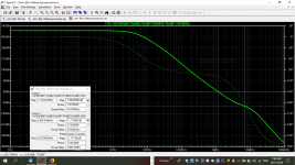
Simulations show that the high frequency response with the original slow 2N3055's is pretty poor.
Exactly. In my simulations I noticed that THD rise up for the frequencies higher than 10k. I used 2N3055 default Ltspice model. I want build JLH 1969 version and I don't know which rout go - 2N3055, MJ15003 or maybe something in to-3P package like 2SD1047 - this one was praised in this thread.
Tell me guys where can I found LtSpice models for newer transistors such as MJ15003, 2SD1047 etc?
I attached THD result and layout JLH1969
Attachments
- Home
- Amplifiers
- Solid State
- JLH 10 Watt class A amplifier