Member
Joined 2009
Paid Member
Of course it blew, the bias current went through the roof. By using a Darlington at the output you increased the effective hfe by at least an order of magnitude, the current source feeding the base junction of this output was then providing way too much current and the amplifier was over biased. This would not have required a simulation to forecast.
Running a simulation in my head, the JLH amplifier is indeed a very good sounding topology. Its implementation is a bit tricky, but can be done without any dirty parts (ICs, regulators, current sources, current mirrors, compensation capacitors, diodes). Using a JFET for the input stage, a video transistor for the VAS and (preferably lateral) MOSFETs in the output stage would make it much easier while reducing distortion.
Greetings to everyone!
I also had the audacity to look for an improvement of my JLH (2005): simply carrying out an "upgrade" of the final transistors passing from MJ15003G to MJ21194G more "modern" and theoretically with better characteristics. I thought in an improvement of the already good results that the amp offers: so it was NOT. In practice the sound aspect has been disappointing; the amplifier has lost its personality, the ability to deal with authoritative signals has been lost, the result is a faint and feeble sound. This, though remaining with the same regulations used in the use of mj15003g. Analyzing the situation accordingly, the big negative difference that leapt to the eye was a noticeable difference of Hfe 50 versus 70 of the old, the other parameters all seem to improve. So I thought, having available a number of MJ21194, try to pair a pair in the Darlington configuration, but after reassembling everything I saw that this type of assembly made me burn the 5A fuse that I put to protect the supply trastormator. At this point I think I'm not able to make any further changes so I would like to ask someone who is able to use the simulators if it were not possible to try to perform a simulation test with the above mentioned modification, to check what can be the causes of the dangerous outcome found. Unfortunately I do not have any knowledge of the simulation tools and if someone lent themselves to the experiment, I think it could be something of common interest. I think it is useful to include the scheme of the circuit in question and I want to clarify that the supply voltage is + -20V and a bias of about 1.5A for each single pair of BJT outputs. I hope someone can help me to continue the experiments, assuming that we can achieve some positive results. Thank you. Greetings!
Mleod View attachment 697248
This circuit was designed to drive Quad Electrostatic Speakers without clipping - see The Class-A Amplifier Site - A JLH Amp for the Quad ESL57.
If you are driving a load of 8R you don't need 3A. Power is calculated from W = I^2 *R. which works out at 1.369A for a 15W output so with 1.5A you have that covered to a greater extent than JLH thought appropriate for 10W into 8R.
Even if you increase that to 2A a single output pair will handle this if you keep the supply rails to the stated level.
While you may be halving the number of drivers you are reducing the load presented to the split load phase splitter. AV =gm times RL where gm is 40m Siemens per m.a. and RL is in k.ohms.
There can be a benefit from driving the driver transistor a little harder but RL will reduce with 2 pairs of outputs. You might have been better off with a single pair of output transistors and stuck to MJ15003.
JLH mentioned that Q1 in his version of the circuit might have been a Darlington type MJ3001 however in this Q2 was part of the constant current load in the JLH2005 this is outside that monitoring loop.
I have simulations of the 1996 version of the amplifier including the stability tests - either transistor type could be used in that version of the circuit.
Last edited:
Greetings to everyone!
I also had the audacity to look for an improvement of my JLH (2005): simply carrying out an "upgrade" of the final transistors passing from MJ15003G to MJ21194G more "modern" and theoretically with better characteristics. I thought in an improvement of the already good results that the amp offers: so it was NOT. In practice the sound aspect has been disappointing; the amplifier has lost its personality, the ability to deal with authoritative signals has been lost, the result is a faint and feeble sound. This, though remaining with the same regulations used in the use of mj15003g. Analyzing the situation accordingly, the big negative difference that leapt to the eye was a noticeable difference of Hfe 50 versus 70 of the old, the other parameters all seem to improve. So I thought, having available a number of MJ21194, try to pair a pair in the Darlington configuration, but after reassembling everything I saw that this type of assembly made me burn the 5A fuse that I put to protect the supply trastormator. At this point I think I'm not able to make any further changes so I would like to ask someone who is able to use the simulators if it were not possible to try to perform a simulation test with the above mentioned modification, to check what can be the causes of the dangerous outcome found. Unfortunately I do not have any knowledge of the simulation tools and if someone lent themselves to the experiment, I think it could be something of common interest. I think it is useful to include the scheme of the circuit in question and I want to clarify that the supply voltage is + -20V and a bias of about 1.5A for each single pair of BJT outputs. I hope someone can help me to continue the experiments, assuming that we can achieve some positive results. Thank you. Greetings!
Mleod View attachment 697248
Hi Mleod.
If I can paraphrase the above replies and add my own experience on this: The constant current source will force a current through the driver transistor suitable to bias the output transistors within a given range according to their current gain. Replacing the output pair with Darllingtons increases the current gain dramatically so you need less current from the CCS and the 50 ohm pot does not give sufficient control to turn the CCS down. If I remember correctly, you need something like a 5K pot in that CCS. Incidentally, all the MJ15003s that I have measured have a Hfe of around 70 to 80.
I have experimented for about 10 to 12 months with different configurations of the JLH including the Darlington output pair - have a look at JLH-D16 - whilst still keeping to the JLH 'architecture'.
I have also experimented with changing the output pair and/or the driver to CFP or Sziklai pair and various output power levels.
My experiments show that you can get the distortion down to quite low levels around about 0.0018 on the bench. Listening is something else and I choose to make my judgement using a mixture of bench measurements and losts of listening. I always seem to come back to the circuit that you originally used which is the final JLH circuit modified by Geoff Moss with 2 pairs of output MJ15003s. It just sounds so good to me. But it needs to have a good heatsink to go with it. To quote Rod Elliot "You can never have a heatsink that it too big" and some of the JLH kits/ready-builds I have seen are woefully inadequate in the heatsink area. I am currently finalising my eventual build and will post some pictures when I have one of the channels complete. I have adopted an approach of separate channels with the PSU for both of them in a separate case. Although I will probably go for 2 output pairs using the MJ15003, I have designed the implementation to be able to use 3 or 4 pairs.- I am what we call a 'tinkerer'.
")
I have a pet theory, with abosolutely no theory or measurements to back it up, that the audio amps that sound very good, have the minimum number of amplifying stages. My reference for this is the EMI TG mixing console, (and probably the Neve series as well) which is accepted as one of the finest ever designed, and uses very few single transistor stages, so the JLH appeals to my pet philosophy as well as appealing to my ears.
Somewhere in the JLH thread, I have posted a spreadsheet that details the voltages and currents for various output powers and number of output pairs. Let me know if you cannot find it and I will try and find it on my computer.
So my advice would be to play around on the bench a bit. Look at the JLH Darlington thread and then take a long time to listen with your favourite music. When you find what you want and like, go overboard with the heat sinks.
Happy listening
Mike
GREETINGS AND THANKS TO ALL FOR YOUR ANSWERS !!!
Hi Mike!
I think you have exactly grasped the meaning of my speech and in particular the problem related to CCS: I assumed some adaptation was necessary and I will bear in mind the suggestion you gave me (replacement of the 50ohm pot with a 5K pot). I then read some posts you have indicated with a lot of interest also relatively to the Sziklai pair. However, my idea would be slightly different: I thought NOT to pair a MJ15003 with a BD139-16, but a pair of MJ21194 with each other with the intent of not completely overwhelming the circuitry (increase of HFE not exaggerated) and have a better allocation thermal (maintaining the bias current similar to that of a single bjt as originally). This with the idea of making more airy and weight to the sound performance (my real goal) given the deficit shown against MJ15003 (among those I have used so far HFE max 70 with a minimum of 48, ... bad lucky?). Here is described at the bottom of the question and the objective of curiosity and given his great experience I would like to know what his opinions on it and if you could give me some indication to be able to practice in practice something that works and experiment.
Many thanks and greetings.
Mleod
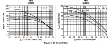
To have some parity with datasheet specifications, Hfe measurements should be performed at a typical collector current for the application. The reason being that most transistors have widely varying Hfe with current, as shown in the example graphs below.
Little battery operated testers and some multimeters can only measure Hfe at the tiny level of about 2 mA which is probably fine for small signal transistors but completely unrealistic for power transistors, where 0.5A Ic is often used for simple testing for home audio use. This also requires they be on heatsink.
Little battery operated testers and some multimeters can only measure Hfe at the tiny level of about 2 mA which is probably fine for small signal transistors but completely unrealistic for power transistors, where 0.5A Ic is often used for simple testing for home audio use. This also requires they be on heatsink.
Attachments
My experiments show that you can get the distortion down to quite low levels around about 0.0018 on the bench. Listening is something else and I choose to make my judgement using a mixture of bench measurements and losts of listening. I always seem to come back to the circuit that you originally used which is the final JLH circuit modified by Geoff Moss with 2 pairs of output MJ15003s. It just sounds so good to me.
Mike
Re the last point the circuit shown in post 4981 has a constant current load feeding the voltage stage - said to be the JLH2005.
I looked at the circuit by Geoff Moss designed for use with Quad Electrostatic speakers which has a 2002 date and differs from the former in having a bootstrap collector load. There seems to be a missing history in between the dates.
Attached is a simulation of Geoff Moss variation using a different transistor line-up with Cordell .models - the current adjustment to increase Iq can be made by reducing the value of R3.
Feel free to replace the bootstrap by a constant current load.
Feel free to replace the bootstrap by a constant current load.
Attachments
To have some parity with datasheet specifications, Hfe measurements should be performed at a typical collector current for the application. The reason being that most transistors have widely varying Hfe with current, as shown in the example graphs below.
Little battery operated testers and some multimeters can only measure Hfe at the tiny level of about 2 mA which is probably fine for small signal transistors but completely unrealistic for power transistors, where 0.5A Ic is often used for simple testing for home audio use. This also requires they be on heatsink.
To add the point made here - standard specifications are based on temperature at 25C however mobility of electrons will increase when this rises.
The formula for gm =Ic(q/kT) where q is the charge on the electron, k is Boltzmann's constant and T is the absolute temperature.
If a transistor lacks in gain some of that can be made up for my running the device at a higher temperature - noting the MJL21194 is a 200W device but above 25 degrees C that rating decreases by 1.43W per degree C increase in temperature.
The temperature increase can be substantial with Class A operation so these figures need to be balanced against the choice of heat sink specification and the local summer climate.
I have a pair of heat sinks rated at about 0.4 degrees C per W of heat dissipation. These have to dissipate 88 W each for two channels. The heat sinks can get to 60 degrees C in summer.
The current draw is 2A per channel. The transformer is rated at 300 VA and this can also contribute to the heat.
When the sums are done on heat sink requirements be generous - sometimes heat sinks don't live up to the specified ratings.
Attached is a simulation of Geoff Moss variation using a different transistor line-up with Cordell .models - the current adjustment to increase Iq can be made by reducing the value of R3.
Feel free to replace the bootstrap by a constant current load.
Prasi may have PC boards for this amp
in case you interestedRunning a simulation in my head, the JLH amplifier is indeed a very good sounding topology. Its implementation is a bit tricky, but can be done without any dirty parts (ICs, regulators, current sources, current mirrors, compensation capacitors, diodes). Using a JFET for the input stage, a video transistor for the VAS and (preferably lateral) MOSFETs in the output stage would make it much easier while reducing distortion.
Interesting, but i think that a latfet cannot sufficiently be driven by a phase splitter using even something like sc3503.
Oops sorry, you didn't mention a latfet at all. Yes, mosfet is possible. my simulation was very good but i have never built the design.
lol, indeed you mentioned latfet
Last edited:
GREETINGS AND THANKS TO ALL FOR YOUR ANSWERS !!!
Mjona: thanks for the fail that you sent me, but unfortunately I can not give a meaning to the codes it contains, please could you tell me where I could find the system and the method to decode it?
Gaborbela: thanks for the indication on the PC board of Mr. Prasi, however, the amplifiers I made them on the sideburns, as it was a time (given the frequencies in play it was not necessary to devise a particularly studied lay-out), and they work perfectly. Only having to use Bjt with much higher Ft, it would be necessary to resort to specific PCboard.
However, I would really like to experiment with the construction of a pair of MJ21194 in Darlington, as I have several of them, and beyond the disquisitions if the experience can be appropriate or not (regardless of temperature problems because I have sinks of heat rather large and numerous, surplus) the curiosity of being able to express a judgment, on the strictly sound level, remains. So if someone had the opportunity to give me some suggestions on how to proceed or to address some site where the problem in question is addressed, if you can make a simulation that can give some indication of the methods of action to achieve this goal, I would be really grateful.
I wait for some indication, thanking for the attention, greeting all of you cordially.
Mleod
Hello again Mleod.
If you are going to experiment a lot I strongly suggest that you get yourself a variable bench power supply capable of +/- 30 volts and up to about 2 Amps with a current limiter. This will make trouble-shooting a lot easier and save you time and money in the end.
With regards to using Darlington output transisitors, the first suggestion I would make is to change VR2 to a 2K variable resistor in series with a 100 Ohm fixed resistor. This will allow you to adjust the bias current to smaller values. If this does not give you the range of adjustment you need, then try a 5K variable with a 220 ohm fixed. You make also have to change R6 from 4K7 to a 10k ohm. Start with just one output pair and gain success with that before moving on to other things.
You will also get an increased power supply rejection by changing R3 to 2 x 4k7 with the junction of these going to the + rail through a 47uF capacitor (+ve of the capacitor going to the + rail) - this is detailed in Geoff Moss's articles in the Class A web site.
On a general note, keep the zero volt line with the input ground and feedback circuit seperate from the ground connection of the decoupling capacitors (C4 to C7) and take them both by separate wires back to the power supply. Also, in all my experiments, I have never had to include a Zobel network R13/C8 so you could probably get away without it.
I hope this helps you.
Kind regards
Mike
I've not seen the PNP version before so I am interested in how you are going.
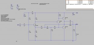
I ran the supplied .pdf circuit into LTSpice and got the following*:
250 ohm to bias at 1Amp.
Max potentiometer value of 100K yields balance voltage at 9.6ish volts.
Maximum voltage in before clipping: 0.75v
THD @1khz = 1.5% into 8 Ohms
THD @1khz = 2.4% into 4 Ohms
Harmonics are predominantly Odd into 8 Ohm, Even into 4 ohm.
---------------------------------
What impedance are your speakers?
I can't decipher what the value of C30 is. Can you please tell me so I can update the model?
The distortion figures seem quite high compared to similar NPN models I have run and the one I built.
Thanks for the feedback
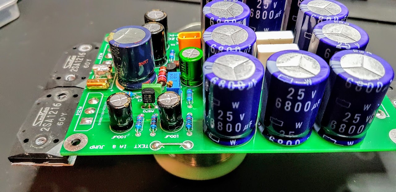
I'm embarrassed to admit 1/2 the problem was my new "Ultra Premium 2 RCA to 2 RCA", the signal seems to be slightly shorted and the JLH is pretty sensitive... the weird thing is that it didn't exhibit the issues previously or with my Class D amp, which threw me.
Additionally I soldered an LED to the TP points to get V to the power LED, not sure if that had a negative impact.
My JLH 1969 still sounds bad (huge distortion with any audio that has lots going on) on both channels; it plays OK with simple/quiet tracks.
It it still sends un-amplified distorted signal to the speakers from the preamp while not powered on.
I still couldn't bias to 1/2 the 20.4v.
Speakers: Klipsch RP150M's (8Ohm).
Preamp: Yamaha WXC50 > miniDSP > JLH1969
I put the ACA amp back in... plays great now... even with my "Ultra Premium 2 RCA to 2 RCA" PoS if I bend the cable right.
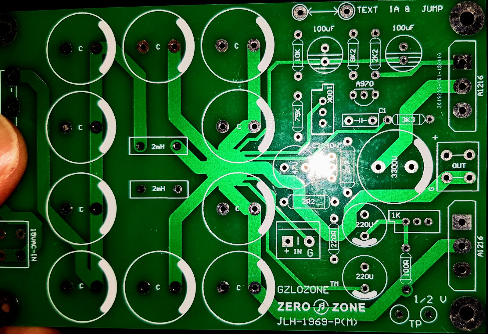
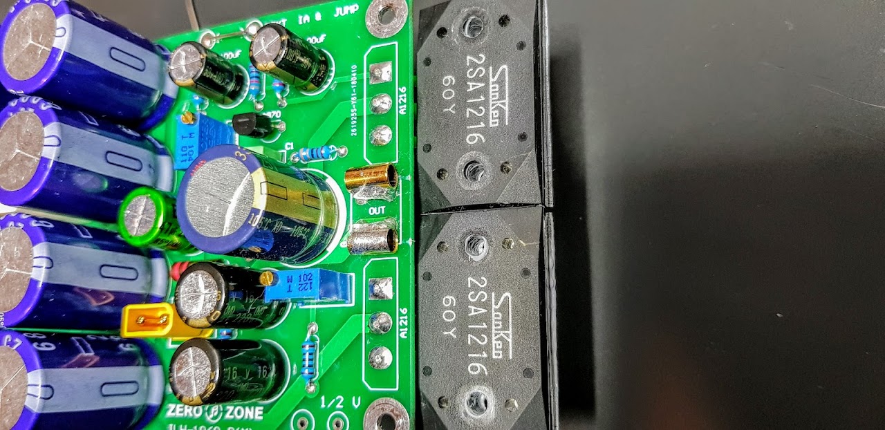
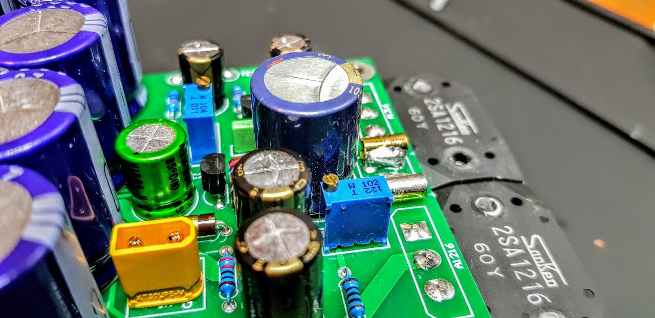
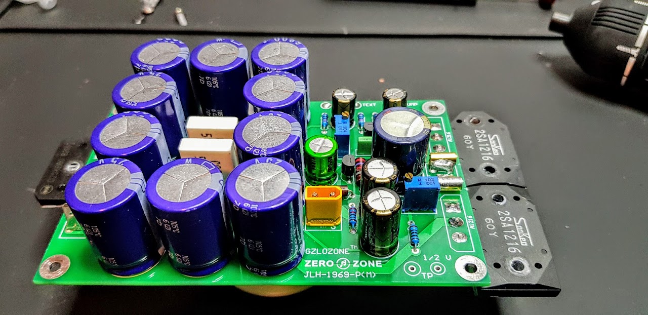
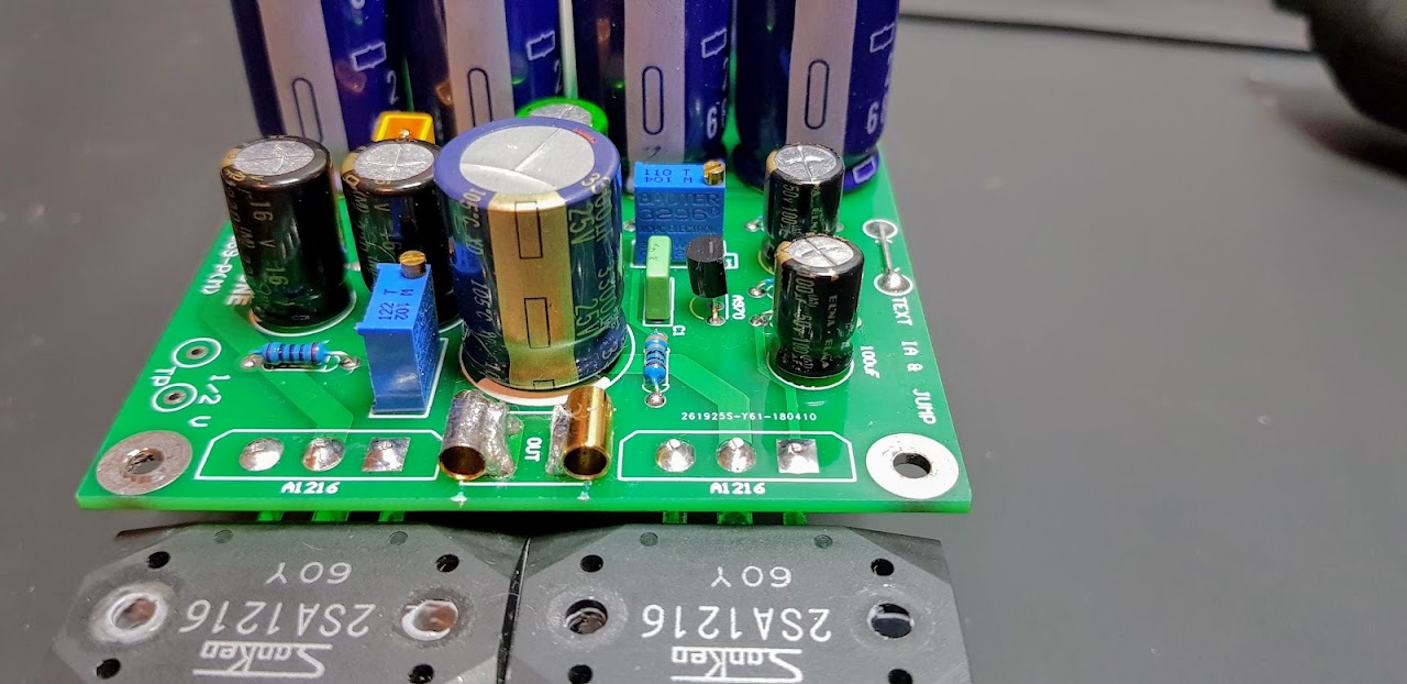
Here's a pic of the board which gives you all the values:
GREETINGS AND THANKS TO ALL FOR YOUR ANSWERS !!!
Mjona: thanks for the fail that you sent me, but unfortunately I can not give a meaning to the codes it contains, please could you tell me where I could find the system and the method to decode it?
However, I would really like to experiment with the construction of a pair of MJ21194 in Darlington, as I have several of them, and beyond the disquisitions if the experience can be appropriate or not (regardless of temperature problems because I have sinks of heat rather large and numerous, surplus) the curiosity of being able to express a judgment, on the strictly sound level, remains.
I wait for some indication, thanking for the attention, greeting all of you cordially.
Mleod
View attachment 697723
The simulation material I use came from Bob Cordell's website - see CordellAudio.com - Tutorial Simulations where you will find a zip file with all you need to use provided you also down load the .model text files for the transistors and keep them in a folder suitably named so you can access this if you are working offline.
If you hover and click over the .inc statement you can browse through your files to identify the location on your computer and click on that so the path is shown in the search field and save that in your simulation.
If working online you can use the .inc include statement in the simulation of mine in post 4989 this will do the same.
If you are looking to do a Darlington build you should ask John Ellis - that said his circuit is a significant step up in complexity and if you were get something wrong you could find yourself in a bigger quandry than you are at present.
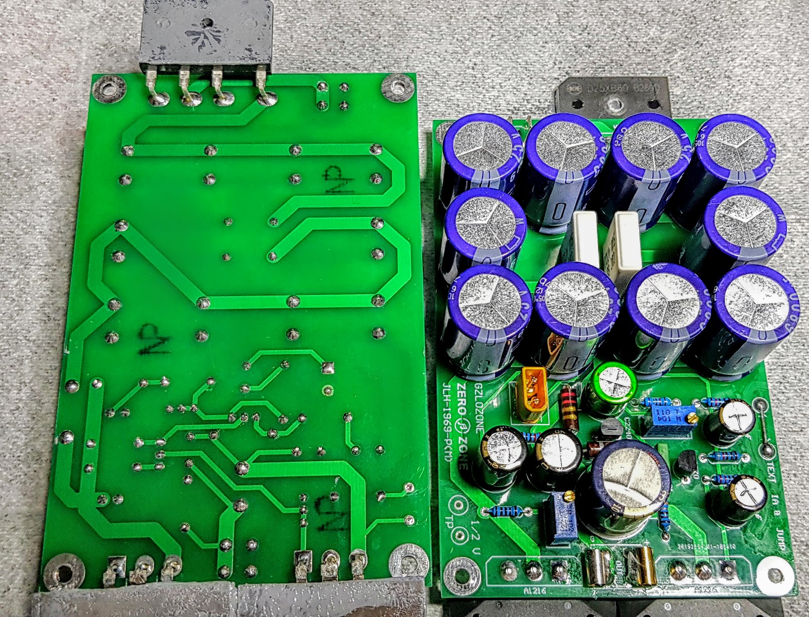
Do you have a close up pic like that of the built up boards both sides?
Distortion seems high, suspect too near clipping.
Thanks diyaudio - SPICE models for the devices found on these threads!
Simulation at 23V supply, 10V peak into 8 ohms 0.08% at 1kHz.
Data sheet shows slight decrease in gain at below 2V for 2A current, hence with approx. 11.5V per side I limited the output to 10V peak, 8 ohms.
Comparison with NPN (2N3055 (epi)) output THD at 10W (30V supply) 0.24%
Transistor currents illustrated for 3055. 22% distortion, mostly 2nd harmonic, in each!
Hi John
I wonder if you could share a screenshot of your sim schematic? I am having trouble getting mine to show distortion less than 1.3% based on the schematic Raybies posted that was presumably included with the kit.
I can't find any information regarding where this PNP version popped into existence. Perhaps ZeroZone had excess A1216 that needed using up
Attachments
- Home
- Amplifiers
- Solid State
- JLH 10 Watt class A amplifier