One reason to like a capacitance multiplier is the minimal heat output the pass device might suffer. In theory it might only need to drop 1V to work. It might be optimum at 1.3V. This is because the first part of the transistor current amplifying curve is not as good as slightly higher up. I think I have had OK results down to 0.8V.
The thing to realise is if the volts dropped ( Vce) is fixed one can be sure nothing will change much in that area ( that is when not using the zener ). That might be very good or it might be very bad if not thought through. With the option for a zener a choice can be made. Mostly allowing the pass transistor to get hot rather than the JLH is the better option. If you find a very tough cheap transistor like TIP35/6 I would say don't bother with anything else. This amplifier won't need it. It is valid to think of the pass transistor. It is almost like a cascode to nowhere. In valve designs where a N type MOS FET is best some second harmonic distortion is seen. This is a nice harmless thing. That's not to say it's not there. I would say you will more likely hear capacitor quality than pass transistor. It's almost like the transistor is just a resistor. This is mostly so as it's work is over by 1 kHz and the amplifier decopling cap takes over. I can see the arguelment goes either way on that, hence I say it.
Let me qoute the valve design in mind. It was found for a relaible circuit using different MOS FET's 8V drop was required ( far more than bipolar types ). I max was 140 mA, V max 510VDC. A 600 V MOS FET seemed to work when some precaution of the gate drive was taken. The heat output was OK at 1.12 watts with no heatsink. As it was a T0220FP package simply bolting it to the chassis was enough to work very well. The change is noise was about 30 dB and cost pennies. Final noise was -88 dB referece 1 watt. - 60 db hum would not be OK without it. Ripple was about 490 mV peak to peak before the FET. 8.4 mV after. The loss of 5dB being heater noise ( -35 dB ). 11 uF and 10K to the Gate with with 2 x 1M to share the 460V between 2 x 22uF. I would not recomend a FET for the JLH. Nothing to do with good or bad, just which suits best. If you don't mind working a bit harder the FET will be fine and will be super fast. That 8 V might be realistic or at least 5V. The thing to note is that 8V 140mA never changes as like JLH it is class A as it was in 1930 in that amplifier. As I go from house to house it will never change. All that will change is maximum output in various locations. That is factored in often by looking at the anodes in a darkened room. Eg 27 watts for EL34 and is it red, if so try 24 watts. KT88 and EL37 also used. The valve forms a constant current device due to cathode resistor. The resistor remains more sophisticated than modern ideas. It auto adjusts nicely.
A FET source folower should be very transparent as it is so very close to being a resistor. It needs a seiers resistor at the drain to which should be I = Vpsu/r = I max FET. 1 ohms might be OK for a 40 amp type. The FET might need to get rid of 15 watts with a JLH. The bipolar 5 watts.
Last edited:
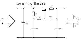
The input side of the capacitor multiplier must be greater than about 1V by at least the ripple voltage on the main smoothing capacitor, or the ripple will just feed through.
So the power dissipation won't be as low as perhaps suggested. That is why I would recommend a stabilised PSU rather than cap multiplier, but both have to stave off the ripple voltage and therefore the difference in dissipation in the pass transistor won't be much if anything.
I'd agree that an input choke filter is ideal for class A circuits and would serve to reduce the ripple voltage by at least 10x (whether used as an input choke or as part of a CLC (pi) filter). That could make a cap mag very useful.
Choke design is quite fun - the air gap calculation is the more challenging for D.C. handling chokes, but not so much when trying to find suitable iron cores these days - EI seems to be a dying breed, toroids tend not to have air gaps (not without a hacksaw at least) and home winding is troublesome.
That's right. I think what people will do knowing how this thread goes is use 30 000 uf then add the capacitance multiplier. What I should have said is 1.3 V plus whatever ripple peak to peak.
I just had a thought. And yes it's been thought of. I have never tried it. LD1084 could be used. A regulator as capacitance multiplier.
https://www.ednasia.com/news/article/lm317-cleans-up-but-doesnt-regulate
I just had a thought. And yes it's been thought of. I have never tried it. LD1084 could be used. A regulator as capacitance multiplier.
https://www.ednasia.com/news/article/lm317-cleans-up-but-doesnt-regulate
Also a shunt regulator. Here again a LM317 is able to do something unlikely.
https://www.edn.com/design/analog/4422122/Power-Zener-using-the-LM317
https://www.edn.com/design/analog/4422122/Power-Zener-using-the-LM317
Hello everyone,
I faced the problem: 100 Ohm resistor (R1 on original schematics, for 8 Ohm load) starts heating as hell when bootstrap capacitor (C1) is connected. The resistor is rated 1/2 W, but it becomes so hot so it burns fingers and starts smell! When bootstrap capacitor is disconnected (glad I figured out to do this), the heating disappears. Measurements without the cap show current about 25 mA, with the cap it's kind of the same, but I think it's just my multimeter ignoring high frequency oscillation.
Did anyone face that? Power transistors (MJ15003G) are on short (10 cm) wires, preamp is BC560C/BD139. The problem is also reproduced on the second channel. The bootstrap cap is Panasonic FC type 470u/50, checked to be good (no shorts, etc.)
It does sound like oscillation. The cause could be layout and the return of grounds to the PSU or it could be down to the more modern semiconductors. Or a combination of the two.
You could try adding a normal Zobel network of a 0.1uF and 10 ohm from output to ground. Connect the network before the speaker coupling cap and not after. Also try adding a small cap across the 2700 ohm feedback resistor. Try 47pF or 100pF and see if it helps.
You could try adding a normal Zobel network of a 0.1uF and 10 ohm from output to ground. Connect the network before the speaker coupling cap and not after. Also try adding a small cap across the 2700 ohm feedback resistor. Try 47pF or 100pF and see if it helps.
Thank you. So I have done the signal ground plane right?
Also, I see you use 2SA970 on the input, would it be an improvement over BC559 or its negligible?
Hello Cerniu,
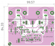
here is something I drew quickly. Although not very optimal, I always like to keep signal traces as short as possible. Height of PCB can be made smaller too, lots of open areas.
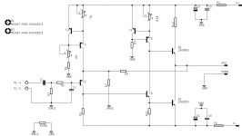
I drew the ckt as per fig 2 of The Class-A Amplifier Site - JLH Class-A Update
A very nicely compiled site as shared by Ian Finch.
It also informs on how to connect grounds of amp to PS and SPK grounds.
Pl dont take it as final for your layout, make your own after reading thro the link.
regards
Prasi
edit, i used BC560 cbe transistors for to-92 instead of 2sa970 in the layout.
Attachments
Last edited:
I wonder if the cmx as given by ostripper would be useful here diyAB Amp - The "Honey Badger"
for the i/p as informed by bigun.
for the i/p as informed by bigun.
Last edited:
Hello Cerniu,
here is something I drew quickly. Although not very optimal, I always like to keep signal traces as short as possible. Height of PCB can be made smaller too, lots of open areas.
I drew the ckt as per fig 2 of The Class-A Amplifier Site - JLH Class-A Update
A very nicely compiled site as shared by Ian Finch.
It also informs on how to connect grounds of amp to PS and SPK grounds.
Pl dont take it as final for your layout, make your own after reading thro the link.
regards
Prasi
edit, i used BC560 cbe transistors for to-92 instead of 2sa970 in the layout.
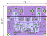
arrangement of components near i/p, heatsinks for the T5/T6, reducing the size a bit and placing a contiguous ground plane on top (blue) results like this.
regards
Prasi
Attachments
It's interesting to simplify the current setting like that. In a way it's no different to a class AB over driven into A. The difference is with JLH it is vital to nail that current +/-10%. With AB it only is important to get it +/-25% as long as -25% is > 2 watts and +25% isn't too hot. The downfall of the JLH is it will not do AB. I have to say I have never questioned AB as to current stability before, it can be no different as the control method is crude. It's no better than the JLH although usually temperature adjusted. The current source should work like the Sinclair Z30/AR A60.
JLH would have looked at his design very carefully. I suspect simple is best.
JLH would have looked at his design very carefully. I suspect simple is best.
Thanks for the suggestion, it really was an oscillation. The reason was the fact the input wasn't connected - after connecting a potentiometer to input the heating disappeared.It does sound like oscillation. The cause could be layout and the return of grounds to the PSU or it could be down to the more modern semiconductors. Or a combination of the two.
You could try adding a normal Zobel network of a 0.1uF and 10 ohm from output to ground. Connect the network before the speaker coupling cap and not after. Also try adding a small cap across the 2700 ohm feedback resistor. Try 47pF or 100pF and see if it helps.
Would like to ask about idle current value - how much should I rise it to keep distorsions on about the same level as with 27v supply, if I'm using 24v supply?
Idle current depends on the load impedance you want to drive. Running on 24 volts might just about get you 10 volts peak output voltage, maybe even a fraction more, and that is a peak load current of around 1.25A which is slightly more than the recommended bias for a 27v rail. The reason for that is modern devices might just allow a little more peak to peak voltage swing than the older transistors.
So the simple answer is that what applied to 27 volt will also apply to 24 volt.
So the simple answer is that what applied to 27 volt will also apply to 24 volt.
Is there any benefit of increasing idle current at all? I'm going to drive 8 ohm load.So the simple answer is that what applied to 27 volt will also apply to 24 volt.
Thanks - this is really the answer I was needed!No benefit at all if the load is 8 ohms. All you will get is more heat dissipation.
") I was tuning the circuit to 1.8 amps and was just about getting a bigger radiator, because it's heating too much.
I was tuning the circuit to 1.8 amps and was just about getting a bigger radiator, because it's heating too much.A bit aside question - did anyone tried Aishi RS cap series? On paper they are even better than Panasonic FC series, though looking much cheaper IRL
The JLH, in common with several other designs of the same era, use high value resistors in the input bias chain. That will cause the input stage frequency response to be reduced, or phase shifts increased at a given frequency, which is one reason to use lower value resistors (e.g. a 10k instead of 100k's) but the solution most people use is simply add a capacitor of about 100pF to the input (input to ground). It will affect the bandwidth dependent on the pre-amp impedance but as long as it is "high enough" should keep the impedance low at high frequencies, and reduce the risk of oscillation.
The JLH, in common with several other designs of the same era, use high value resistors in the input bias chain. That will cause the input stage frequency response to be reduced, or phase shifts increased at a given frequency, which is one reason to use lower value resistors (e.g. a 10k instead of 100k's) but the solution most people use is simply add a capacitor of about 100pF to the input (input to ground). It will affect the bandwidth dependent on the pre-amp impedance but as long as it is "high enough" should keep the impedance low at high frequencies, and reduce the risk of oscillation.
Can lower value resistors be used as drop in replacement for the original 1969 schematic? To what value the 39k resistor in series with those 100k bias resistors should be changed?
- Home
- Amplifiers
- Solid State
- JLH 10 Watt class A amplifier