Would you say that the 60kHz noise is less than the 120Hz/240Hz etc noise from a full wave rectified transformer which lies in your bass region. The 60kHz noise you will never even know about.
If you are worried that there would be noise injected into your CD player and other equipment via the mains then it would be best to unplug every SMPS in your household such as your PC, TV, DVD maybe even your CD, phone charger, Laptop chargers, low voltage light transformers, CLS lights and the like.....")
If you are worried that there would be noise injected into your CD player and other equipment via the mains then it would be best to unplug every SMPS in your household such as your PC, TV, DVD maybe even your CD, phone charger, Laptop chargers, low voltage light transformers, CLS lights and the like.....
Days of listening the "JLH", and I am sure, it is a bit milky, reserved. Compared with the 3-parts-SE. PSU nearly the same. It is the experience, again and again, the more (active too) parts, the more opaque, obscure;-? (3 active) parts, even if the same, are audible.
It seems, my memory of listening, hearing, is prolonged more than some seconds;-)))
It seems, my memory of listening, hearing, is prolonged more than some seconds;-)))
SMPS + supporting big capacitance;-?
Of course. I run 2 x 10 000uF per rail after the SMPS. Having too to big caps will cause a smallish SMPS to shut down.
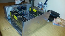
On this version of the Hood, I am using two very cheap 24V/5A SMPS bought on eBay for about $8 each advertised for LED lighting. They work absolutely fine for several years. I built many Hoods over the years and the amp is only as good as its supply.
I also have a Hood running of a large Meanwell but I believe the Meanwell too expensive. SMPS has been in PCs since the 80's, it is hard to think that they are not any good.
Attachments
If you look carefully at my graphs it looks very possible that SMPS could work. As mine is the 1969 type it needs very stable voltage to get stable current setting so SMPS is fine for that. 0R33+1000 uF is fine. I agree SMPS and class A looks possible despite 60 kHz residual.
I am looking to build a new oscillator. I have never built the JLH design from 1981. I think this will work once the ideal resistor is found. The idea is to have a gain of 3. This says the lamp will be circa 340R. From a project I did yeas ago it just seemed to work once dialed in. Thought I would like to share his Wireless World design 1981. I have inverted the op amps, his uses 2 x + inputs. Even using 741 he was saying better than the one I am using. The lamp is a non linear resistance which works as an AGC. Any thoughts? It will be a few days before I get some lamps. I did build this as a one op amp type so just assuming I can do this. The idea is to reduce the common mode difference between the op amp inputs when using two. NE5532 is anything you like. Remember it can drive 600R which helps. If I have the phasing wrong etc please say. It should be right ???
http://cpc.farnell.com/sli-ebt/387/6mm-midget-flange-28v-3-8-lumens/dp/SC00314

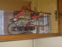
This is what I am using now . I have knocked the gain down a bit ( 470K ). It was for testing my MOS FET JLH tribute amp as a buffer ( gain of 1 ). It was fine doing that? This is my notes to myself so forgive if not clear. Notice NE5532 and TL072. When using a lamp the 5532 was better.
If you look my 1 watt graphs are about the same! Not bad for 47 kHz I guess? I didn't know I had these tests.
i like a buffer idea .
This is what I am using now . I have knocked the gain down a bit ( 470K ). It was for testing my MOS FET JLH tribute amp as a buffer ( gain of 1 ). It was fine doing that? This is my notes to myself so forgive if not clear. Notice NE5532 and TL072. When using a lamp the 5532 was better.
If you look my 1 watt graphs are about the same! Not bad for 47 kHz I guess? I didn't know I had these tests.
i use a mbl 6010d clone with very good result .
no more gain but perfect impedance adaptor , particulary with simple amp schematic
If you look at my graphs the noise is getting to the distortion levels. As TL072 is a JFET device we win more than we loose. The problem I was having was to make a simple circuit I could adjust on one side of the oscillator. As you can see it's very OK. The output was clipping the second stage ( +/- 15 V PSU ). So the answer was an inverting high resistance input ( some distortion reduction due to antiphasing also ). This reduced the output and filtered harmonics free of change, hence an octave below. Whilst it is not a pretty circuit it worked. In this rare example TL072 won the war. I did try an active stage. The passive was easier.
People say heat sinks are very expensive. I found these below. You could use 4 if SMPS and 1.2A 27V ( try 30 V I would say ). 5 if you have luck with a regulator being in the ideal voltage range. 6 if the transformer is a bit high on voltage. I like this type as heat escapes both sides. My Voltcraft PSU has the same. I usually find flying wires to the transitors OK when simple circuits. Whist they are borderline on size they are a very good price. From what others say I suspect many use undersized ones. Call your room 30C and you should never go above 55C heat sink temperature as the rule of thumb. Usually 55C is about hand hot. The transistor cases will be higher. If we say 15 watts per device that's about 51C if 1.2 amps. I suspect in the real world that's what you will get.
SK02-50-SA | Heatsink, CB, TO-3, 1.3K/W, 50 x 115 x 63mm, Screw | Fischer Elektronik
BTW. Some people will not realise the capacitor C1 220/470 uF going to R1-R2 typically 100-560R if 8R is what we call a bootstrap current source ( I copied a circuit with 2500uF! It's OK ). Some people will look at it and say no way we can use that. However the specs are vastly better because it is there and very close to an ideal current source. Thus the 2N697 ( Tr3 ) is doing so many tasks and doing it with precission. The only small defect of the design is also it's reason to be. It needs a very quiet voltage stable PSU. This will be my next task.
I have a very cunning plan if you have to use a switch mode PSU. Make sure you run your CD/DAC from a long cable to another part of the house. This way you use the house wiring inductance and resistance to make a sepparation. It will make a difference and costs nothing, I learnt this in 1982 from a friend who insisted I listen. As this is class A and SMPS is OK on reduced voltage you could use a filement lamp and 2 x 470 nF class X2 as a Pi filter. It might work and avoids the long cable. As the filement is designed for 230V it is of no great importance if the in rush is like a 0 ohm load. It might defeat the SMPS low voltage detector ( usually > 90 Vrms, try 100 watt type ). If any try this say what you get. It should work. The lamp also is fun to match.
I really admire this project. It is exactly what you should never do. Brave. It shows just how remarkable the JLH is. He has other stuff
Germanium Power Amplifier
Germanium Power Amplifier
Last edited:
i don't realy understand the interest for the germanium !I really admire this project. It is exactly what you should never do. Brave. It shows just how remarkable the JLH is. He has other stuff
Germanium Power Amplifier
if it continues, we will end up making amps with flint
ten pointIt is like coffee;-)
Like Arabica or/and Robusta. Different flavour, savour, character - independently from cultivation, region, climate ... year;-)))
I have a DA15 wreck in my home but I can not decide to dismantleWill replace the bipolars with germaniums. "JLH" within the Mitsubishi DA-A10DC-case. And tell the differences;-)
Next days;-)
- Home
- Amplifiers
- Solid State
- JLH 10 Watt class A amplifier