Colin,
This is my first attemp and could be wrong.
Hi, if anyone see anything wrong please correct me .
The new parts VR2, Q7, Q8 and R12 is from the updated JLH for ESL.
Parts removed from the original ESL pcb overlay are R5, C4, C4a, RV2.
See attached
Regards,
Chris
This is my first attemp and could be wrong.
Hi, if anyone see anything wrong please correct me .
The new parts VR2, Q7, Q8 and R12 is from the updated JLH for ESL.
Parts removed from the original ESL pcb overlay are R5, C4, C4a, RV2.
See attached
Regards,
Chris
Attachments
Star earth
Chris,
In my opinion you should try splitting and creating several ground points, connecting them all to another single point working as your amp star ground.
To start with, the speaker's (-) point should be connected to the star ground. The input and the grounds bypassing V+ and V- should also go to that point.
Maybe other experts here have a different opinion.
Carlos
JLH PCB
Hi Chris
Thankyou for sending me the updated of the PCB I had a go and nearly got I right .In fact I congratulate may self as my furst attempt at drawing out a PCB. I have built some Kits before but PCBs and parts have been supplied This is my Furst Go at building from the ground up
So thanks again
Colin
Hello,
I'm new in this forum so please excuse me me if I missed smthg. I have few questions:
As for very beginer it would be easyiest way to built JLH by buying some old defected amplifier and to put selfmade schematics into it. For example I have Yamaha A-400/500. It has a lot of free space inside and big regular transformer and big heatsink.
The only problem is that all around amplifiers have +-45V or +-50Volts.
I'm wondering if there are somebody who can help like me in this case, maybe it is possible to calculate JLH 10W schematics for +-50Volts, please?
Kind regards from Lithuania,
Kestutis Rimkevicius
kesrmk said:
As for very beginer it would be easyiest way to built JLH by buying some old defected amplifier and to put selfmade schematics into it. For example I have Yamaha A-400/500. It has a lot of free space inside and big regular transformer and big heatsink.
The only problem is that all around amplifiers have +-45V or +-50Volts.
I'm wondering if there are somebody who can help like me in this case, maybe it is possible to calculate JLH 10W schematics for +-50Volts, please?
Using an existing case and transformer for a new DIY project is an excellent way to begin. But maybe not for class-A high voltage projects.
First of all because you will need a high current amp, which most likely is not what you have now.
Second because you will need lots of heatsinking to dissipate the heat.
So if you want to go the JLH way you will just use the box and some parts, but not the transformer.
What you can do is try ways to upgrade the Yamaha or put a class AB DIY project inside that will let you use that tranformer.
Carlos
It's not practical to modify the JLH for +/-50V rails. You could use the original single-ended power supply version. You would then only use the +ve side of the supply, not the -ve side.
[Actually, I have a schematic Geoff Moss sent me to run the new JLH version from a single supply; email me if you're interested.]
Another idea: I'm hoping to use two transformers, each originally used for a 80W/ch Class AB amp, for the JLH. What I'm going to try is to run the primaries in series (giving each amp half its normal primary voltage), and put the secondaries in parallel (probably with some current-sharing resistors). I do this so the transformers share the load equally. I think I might try to simulate this before I wire it up...
Actually, I may parallel the two after they each run through their own bridge rectifier so there's no way one transformer could drive current into the other one. But I digress...
If you assume that you can't exceed the normal rated secondary current, you will only get half the effective VA rating from the transformer by doing this. But I should have plenty for the JLH.
My existing AB amp has +/- 50V rails, so I should get +/- 25; with a capacitance multiplier it should drop to about the right level for the JLH.
An equivalent technique is that some transformers have two primaries that can be wired for 120V or 240V. If you set it up for 240V, and run it from 120V, it is the same effect but you don't have to worry about balancing the load.
carlmart said:
First of all because you will need a high current amp, which most likely is not what you have now.
B]
Sorry, I meant you will need a high current transformer, which probably wasn't what your Yamaha had.
Carlos
Carlos,
I agree, that mine Yamaha is not designed for drive Class A. But Yamaha claims (in webpage) that Yamaha amplifiers is capable to drive very hard drivers. Even as low as 1 Ohm. So I would like to believe, that it is possible to use transformer also on Class A circuit.
Regards,
KR
I agree, that mine Yamaha is not designed for drive Class A. But Yamaha claims (in webpage) that Yamaha amplifiers is capable to drive very hard drivers. Even as low as 1 Ohm. So I would like to believe, that it is possible to use transformer also on Class A circuit.
Regards,
KR
kesrmk said:I agree, that mine Yamaha is not designed for drive Class A. But Yamaha claims (in webpage) that Yamaha amplifiers is capable to drive very hard drivers. Even as low as 1 Ohm. So I would like to believe, that it is possible to use transformer also on Class A circuit.
For each voltage you will need a certain current to get full class-A power.
Even if the transformer is designed to handle 1 ohm loads, that doesn't necessarily mean that it will handle class A all along.
It may probably be able to work class-A up to a certain level and then get into class-B.
I believe that is the way a manufacturer counts their beans.
Carlos
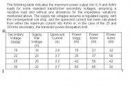
The problem is that the voltage will be too high, resulting in too much power dissipated in the output transistors. See Geoff's table at:
http://www.gmweb.btinternet.co.uk/jlhupdate.htm
http://www.gmweb.btinternet.co.uk/jlhupdate.htm
Attachments
JHL 15 watt Preset Help
JLH Class A 15 Watt Amp Preset Help Post #1
Hi Guys
I am just getting the parts together for the 15 watt JLH As in Fig 2 on Geoff Moss’s Site
My nologe of electronics is not as good as I would like but can build this amp My question is about the Pre sets R1 & R2 as to the position they should be set at be four switching the amp on I am told that R1 should be set in the 12 o’clock potion And R2 set fully ante clockwise before setting up to required Iq
I will be using a 18-0 -18 volt 300 VA transformer mj15003 Trans
1.1 CW Heat sinks as these are the largest that I have
Amp will be running into 6 ohms at about 2.8 Iq
Can you let me now if this is ok?
Thanks
Regards
Colin
http://www.gmweb.btinternet.co.uk/jlhupdate.htm
__________________
CH
Hi All
Just thought I let you now that Geoff has added a new update to his site for the JLH Hopy youre Ampsare sounding good
http://www.gmweb.btinternet.co.uk/jlhupdate.htm#Addendum
Colin
Just thought I let you now that Geoff has added a new update to his site for the JLH Hopy youre Ampsare sounding good
http://www.gmweb.btinternet.co.uk/jlhupdate.htm#Addendum
Colin
Hi Colin,
The fig2 diagram is used in with an Iq of 2A.
The fig3 diagram however must be used in the case you need the Iq of 2.8.
in the Fig 2 version there is about 44w dissipated in each output device. a 1.1K/W heatsink is not sufficient.
in the Fig 3 version with an Iq of 2.8 the dissipation is 25W per device each device its own heatsink should be ok.
One 300VA transformer is on the edge for two channels...
One channel uses roughly 100W for the amp and some in the powersupply.
I've build a dual mono version of the 1996 version and used
2 225VA transformers.
Regarding the position of R1 and R2 I cannot help you.
I'm about to start a new project and go for the fig3 40W into 8Ohm version .
plan is to use a 300VA transformer for each channel.
JLH (update) preset settings
Colin,
Looking at figure 2 the final circuit, RV1 (200R) should be set at mid travel and RV2 should be set at maximum resistance, which way the preset needs to be turned to achieve this will depend on how you have connected it. Remember also that the Iq will increase as the amplifier gets warm, so this will need to be rechecked.
Tim.
help dc offset problem
..with JLH high power version.
Hi,
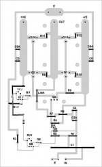
i wired up this version: http://www.gmweb.btinternet.co.uk/jlhesl.htm
i used the same values except of:
q4,q5,q6 - here i used 2sa970,
q3 - here i used 2sc3421,
q1,q1a,q2,q2a - here i used mj15003
all other parts are same os in circuit above.
when i use supply of +/- 20 volts and i regulate the iq to 2,5 ampere - the smallest dc offset i can regulate with vr1 (2k2) is about 850mv. whein i raise the iq to 3 or more amperes the offset goes down to max. 700mv.
it hink the reason could be the changes parts??!!
who can help?
thanks,
Ralf
..with JLH high power version.
Hi,
i wired up this version: http://www.gmweb.btinternet.co.uk/jlhesl.htm
i used the same values except of:
q4,q5,q6 - here i used 2sa970,
q3 - here i used 2sc3421,
q1,q1a,q2,q2a - here i used mj15003
all other parts are same os in circuit above.
when i use supply of +/- 20 volts and i regulate the iq to 2,5 ampere - the smallest dc offset i can regulate with vr1 (2k2) is about 850mv. whein i raise the iq to 3 or more amperes the offset goes down to max. 700mv.
it hink the reason could be the changes parts??!!
who can help?
thanks,
Ralf
ralf i had the same problem as you but mine was low power but high current. To reduce the offset, the resistance must be high, take a resistor and solder it to the variable resistor making the value higher than 2k2 try a 500 resistor or any resistor you have available. It work for me, without the resistor i couldn't go below 400mv but with a higher resistance then proper adjustment can be done. Sometimes the gain of the input transistor and the constant current is way different than of the calculated, bigger values might be needed
JLH 'update' fig 2 offset preset value
While we are on the subject, I have found that VR1 in figure 2 on http://www.gmweb.btinternet.co.uk/jlhupdate.htm is only just large enough if it is 200R. Some constructors might need to increase the value a little. Mine was set at around 190R for zero dc offset.
Tim.
While we are on the subject, I have found that VR1 in figure 2 on http://www.gmweb.btinternet.co.uk/jlhupdate.htm is only just large enough if it is 200R. Some constructors might need to increase the value a little. Mine was set at around 190R for zero dc offset.
Tim.
yepp
...i used a 750 ohm resistor in series to RV1.
Now it works.
i playes the amp few hours and must say the first impressions are very good.
it has more attack in heights than my monster, but it`s not as relaxed as monster.
But: i used as coupling capacitor first a tin foil, then a siemens MKV, 3.3Uf.
I hope that the modification without feedback capacitor and a audionote coupling capacitor could improove the sound.
in moment my Iq is about 2.5 Amperes because my heatsinks are not enough.
i hope that increasing Iq will enhance sound, too.
Whats to do when removing feedback capacitor?
thanks and greets,
Ralf
NickC said:To reduce the offset, the resistance must be high, take a resistor and solder it to the variable resistor making the value higher than 2k2 try a 500 resistor or any resistor you have available.
...i used a 750 ohm resistor in series to RV1.
Now it works.
i playes the amp few hours and must say the first impressions are very good.
it has more attack in heights than my monster, but it`s not as relaxed as monster.
But: i used as coupling capacitor first a tin foil, then a siemens MKV, 3.3Uf.
I hope that the modification without feedback capacitor and a audionote coupling capacitor could improove the sound.
in moment my Iq is about 2.5 Amperes because my heatsinks are not enough.
i hope that increasing Iq will enhance sound, too.
Whats to do when removing feedback capacitor?
thanks and greets,
Ralf
- Home
- Amplifiers
- Solid State
- JLH 10 Watt class A amplifier