Hello,
I am currently building / planning an amplifier project that solely utilizes parts that I have laying around.
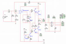
After collecting these parts I came to the following design using an high voltage / power op-amp (OPA453T) + EF output stage.
I currently seem to be biasing the op-amp in class A with roughly 10ma of bias (this was not intentionally designed this way) and this should roughly give me 2.5ma of current to supply the double EF output stage.
The driver transistors will be BD138/137 and the power transistors will be 2SC5198 / 2SA1941 (the TIP41 / 42 in the schematic is just for simulation).
The schematic does not show all the usual rail decoupling caps and other small stuff, but you get the idea.
Any tips to improve upon this design by adding as little amount of parts as possible?
Thanks, Pim
B.T.W Is there any difference in sinking current trough an op-amp or sourcing current when biasing in class A?
I am currently building / planning an amplifier project that solely utilizes parts that I have laying around.
After collecting these parts I came to the following design using an high voltage / power op-amp (OPA453T) + EF output stage.
I currently seem to be biasing the op-amp in class A with roughly 10ma of bias (this was not intentionally designed this way) and this should roughly give me 2.5ma of current to supply the double EF output stage.
The driver transistors will be BD138/137 and the power transistors will be 2SC5198 / 2SA1941 (the TIP41 / 42 in the schematic is just for simulation).
The schematic does not show all the usual rail decoupling caps and other small stuff, but you get the idea.
Any tips to improve upon this design by adding as little amount of parts as possible?
Thanks, Pim
B.T.W Is there any difference in sinking current trough an op-amp or sourcing current when biasing in class A?
Attachments
Attachments
Recommend MJE243/MJE253 as drivers instead of the BD139/140
Mark Johnson is pointing out that you need to add some additional feedback/compensation around the opamp itself, to prevent problems. I have built pretty much the same circuit you have here for headphone use, and the stability is much better if you add some local compensation around the opamp.
In simpler terms, add provision for an R-C network from the -ve input of the opamp, to the output of the opamp. Try 100 ohms + 47pF for starters.
Member
Joined 2009
Paid Member
Not necessarily better, but you could replace the current sink with a bootstrap current sink, two resistors and a capacitor from the output. You could put one on the top of the Vbe chain too. Then to ensure you are pulling or pushing current to the Opamp make one of the bootstrapped sources flow more current than the other by sizing the resistors. Overall you'll lose two transistors and maybe gain a little extra voltage swing.
x2 on Cf. Just a capacitor should be fine with most opamps, it's just low-Rbb' (very low voltage noise) types that tend to prefer an R in series as input capacitance is directly exposed.
Your supplies are low and you've got 10 A output transistors, no need to use 0.33 ohm emitter resistors. (Using Class A bias on the opamp only to spoil it with output stage distortion seems pointless.) You should easily be able to afford 125 mA of bias at 0.1 ohms assuming you've got decent (normal) heatsinking. Also consider going CFP or maybe diamond buffer for increased voltage swing. (Note: When going CFP, emitter resistors travel with the emitter, none are strictly necessary at output.)
Speaking of bias, a series resistor for the adjustment pot is much recommended to keep the amp from going up in smoke accidentally.
BTW, with the extra Pd it won't hurt to give the opamp some decent copper area on its power pins.
Umm... I'd think about that again if I were you. It just prevents the bias transistor from going inductive and is actually bootstrapped.Also wouldnt advise C4 in this design. You are then making the opamp drive a high capacitive load. Consider adding 100R in the opamps output if you want to keep it.
What manufacturer are your BD137/138, Philips? Should be OK then, though you could consider 10 mA of Ic, other manufacturers' 1.5 A jobs can (and quite arguably should) be run a bit hotter. You may need to do some pole juggling between the drivers and outputs (adjust base stopper resistors until drivers are at least 3 times as fast).Any tips to improve upon this design by adding as little amount of parts as possible?
Your supplies are low and you've got 10 A output transistors, no need to use 0.33 ohm emitter resistors. (Using Class A bias on the opamp only to spoil it with output stage distortion seems pointless.) You should easily be able to afford 125 mA of bias at 0.1 ohms assuming you've got decent (normal) heatsinking. Also consider going CFP or maybe diamond buffer for increased voltage swing. (Note: When going CFP, emitter resistors travel with the emitter, none are strictly necessary at output.)
Speaking of bias, a series resistor for the adjustment pot is much recommended to keep the amp from going up in smoke accidentally.
Depends on the opamp, really. Usually has to be determined experimentally. Rule of thumb is npn output is more robust and hence preferred.B.T.W Is there any difference in sinking current trough an op-amp or sourcing current when biasing in class A?
BTW, with the extra Pd it won't hurt to give the opamp some decent copper area on its power pins.
- Status
- This old topic is closed. If you want to reopen this topic, contact a moderator using the "Report Post" button.
- Home
- Amplifiers
- Solid State
- Seeking input on my amplifier design