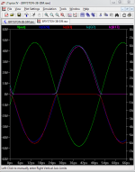
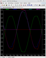
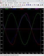
The question came up as to how well the Bryston 3B output stage with both NPN and PNP
finals shared current between the devices. I ran the LTSpice model with 1, 2 and 4 ohm
loads and snap shots showing the current in all 4 output devices are attached for 20 kHz drive.
This model uses Bob C's device model file and I'm not sure if the MJL21193/4 are typical or
not but the sharing is quite good even down to 2 ohms.
Interesting to note that into 1 ohm with the high currents the match is quite bad due to
beta droop in the PNP final device. This shows up both in overdrive and even at high power
but not overdriven into 1 ohm loads. I doubt that the amp is rated for 1 ohm but something
similar might happen with a shorted output and it is interesting to look at anyway. The match
is much better into 2 ohms and up with the reduced output current.
Also interesting, that because there are PNP and NPN finals on both rails that the top to
bottom combined match is quite good.
I wrote a bit about current sharing and the top to bottom match here:
http://www.diyaudio.com/forums/soli...lls-power-amplifier-book-822.html#post5054746
This is the exact 3B, assuming no errors, minus the protection circuitry which is what we
want in order to see the unhindered operation of the amp.
The simulation .asc file is also attached with directives added for distortion analysis, it has
remarkably low distortion.
Attachments
Last edited:
The book, Audio Power Amplifiers by Dr. Arto Kolinummi has been brought to my attention
where the following is claimed concerning the Bryston 3B in a section discussing
non-switching output stages:
"The transistors in the circuit remain forward biased at all times and the circuit can be
thought of as non-switching even if transistor currents may go close to zero." from pg. 232,
and as shown in his Figure 7.36.
This is blatantly false as I've shown in other threads here that Q13 and Q14 for example
have the Vbe junction go reverse biased, that is certainly turned off.
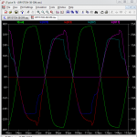
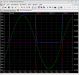
I roughly duplicated his figure in the attached screen snip, the current in all four output
devices is plotted and blown up. They all switch off and I don't see much different than
any other output stage. It is interesting that Kolinummi's figure at the left where time =0
shows the off device as having nearly zero current, but then in the center right above the
"Time" label, the off device shows about 3 times as much current as the other and about
one quarter division on the current axis. I'm not sure how he arrived at that Figure but
both are wrong since in reality the current goes to zero.
where the following is claimed concerning the Bryston 3B in a section discussing
non-switching output stages:
"The transistors in the circuit remain forward biased at all times and the circuit can be
thought of as non-switching even if transistor currents may go close to zero." from pg. 232,
and as shown in his Figure 7.36.
This is blatantly false as I've shown in other threads here that Q13 and Q14 for example
have the Vbe junction go reverse biased, that is certainly turned off.
I roughly duplicated his figure in the attached screen snip, the current in all four output
devices is plotted and blown up. They all switch off and I don't see much different than
any other output stage. It is interesting that Kolinummi's figure at the left where time =0
shows the off device as having nearly zero current, but then in the center right above the
"Time" label, the off device shows about 3 times as much current as the other and about
one quarter division on the current axis. I'm not sure how he arrived at that Figure but
both are wrong since in reality the current goes to zero.
Attachments
Last edited:
Thanks for that, I've been interested in this OPS for a while.
In Bob's thread you asked about how to simplify it, I see Q15 + Q11 (& Q16 + Q10) as essentially one unit, for study of the basics they could be replaced with one transistor.
That makes it rather similar to the corrected illustration from Kolinummi.
Similarly with your comments about the RC network at the base of Q3, strip it out for a check of the basics.
The Bryston circuit has quite complicated interconnections and compensation around the OPS, I would start from basics and study what happens without this complexity.
One idea that occurs is whether it is reasonable to float the connection between phase splitter/drivers Q11 and Q10, similar to the now preferred floated connection of EF drivers, Self's "Type 2" connection IIRC.
Best wishes
David
Simplified Bryston-type OPS
Hi Pete, David -
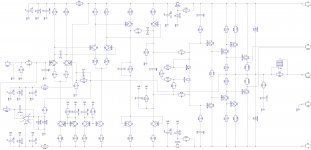
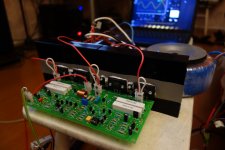
Some years back - in the end of 2013 - I did a project, inspired by a good old Pioneer M3 Exclusive (the front-end topology). I also decided to try a very simple variant of Bryston-type OPS, using the big fast Sankens - see the schematic and the photo.
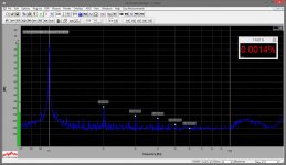
I still use that prototype in my lab from time to time. A very nice sounding amp. Currents distribution within OPS is no problem - there is a slight difference in NPN and PNP collector currents, but rather minor (a few mV difference at emitter resistors - less than 10%). Quiescent current is around 75mA. Spectrum is measured at around 20W @ 8 ohm. Excellent harmonics profile. Some noise floor fluctuation above 10KHz is a sound card artifact - my measurement system at that time was not as good as it is now.
Cheers,
Valery
Hi Pete, David -
Some years back - in the end of 2013 - I did a project, inspired by a good old Pioneer M3 Exclusive (the front-end topology). I also decided to try a very simple variant of Bryston-type OPS, using the big fast Sankens - see the schematic and the photo.
I still use that prototype in my lab from time to time. A very nice sounding amp. Currents distribution within OPS is no problem - there is a slight difference in NPN and PNP collector currents, but rather minor (a few mV difference at emitter resistors - less than 10%). Quiescent current is around 75mA. Spectrum is measured at around 20W @ 8 ohm. Excellent harmonics profile. Some noise floor fluctuation above 10KHz is a sound card artifact - my measurement system at that time was not as good as it is now.
Cheers,
Valery
Attachments
... I also decided to try a very simple variant of Bryston-type OPS...
Hi Valery
Your amp is really a kind of "Quasi-Bryston".
The Bryston has a Common Emitter pre-driver with the phase splitter connected so that one side is CE then Emitter Follower, the other is EF then CE.
Yours has an EF pre-driver so the phase splitter is connected one side EF then EF, other side CE then CE.
That's more or less what a quasi-complementary amp does, except on the positive and -ve sides rather than after each phase splitter.
So the Bryston looks more symmetrical, but that's partly appearance, quasi-comp is better balanced than superficial appearance leads one to think.
But I still think I will simulate the true Bryston as first priority.
Best wishes
David.
Did you study the Bryston connection of the pre-driver?
Not obvious to me what the point is, I will simulate this to study why but always appreciate ideas.
Similarly with some of the compensation, the local loops aren't clear.
Last edited:
Quasi Bryston
Makes you wonder...
A couple of thoughts.
1) Change to class i by replacing the pre-drivers with the LTPs. Error correction and non-switching.
2) A thermal-trak version using the temperature sense diodes to make the drivers (phase splitters) and pre-drivers low impedance. Ensures fast turn on / off.
Not simulated these just some random thoughts at work.")
Paul
Makes you wonder...
A couple of thoughts.
1) Change to class i by replacing the pre-drivers with the LTPs. Error correction and non-switching.
2) A thermal-trak version using the temperature sense diodes to make the drivers (phase splitters) and pre-drivers low impedance. Ensures fast turn on / off.
Not simulated these just some random thoughts at work.
Paul
Thanks for the comments, having looked at the distortion of this amp and the ability to drive
low Z loads I'm starting to like at least the output stage more. I like to see discussion
about something different such as this amp.
Something to think about, Bob C. added a few transistors to provide "error correction" to
his MOSFET amp and in the discussion several people pointed out that it just added more
gain for feedback. One view of this output stage is that a few small signal transistors are
added, providing more gain for local feedback, and even some voltage gain so that less
drive is required from the VAS.
Last night I was thinking about the comp NPN-PNP on each rail and doing just an EF type.
Just looked at Valery's design and it is just that - more food for thought. Question for you
did you have any issues with local oscillation using the very high speed finals in your amp?
Seem to recall that Bryston patented the NPN-PNP comp finals on each rail, anyone know
if it has expired?
Last edited:
Hi Valery
Did you study the Bryston connection of the pre-driver?
Not obvious to me what the point is, I will simulate this to study why but always appreciate ideas.
Similarly with some of the compensation, the local loops aren't clear.
Not sure exactly what you're asking about the pre-driver?
The resistors are there to provide gain for the CFP, the caps set the HF rolloff for that gain.
A pure guess for the RC in front of the "phase splitter" is that the R is to limit the current
drive into low Z loads and the C was just thrown in as a way to take advantage of the R
loss and use it as (perhaps rough) HF compensation.
..Bob C. added a few transistors to provide "error correction" to his MOSFET amp and in the discussion several people pointed out that it just added more gain for feedback...
Those people miss a subtle but important point.
A lot of the "trick" improvements to amplifiers are just as pointed out, simply more gain for -ve feedback.
The error correction scheme is not that simple, is mathematically different.
But your point is correct for the Bryston scheme.
It does, however, seem to work pretty well, I ran some simple simulations yesterday and it makes a decent amplifier with no IPS or VAS at all!
Not sure exactly... the pre-driver?
It would be obvious to power the pre-driver and phase splitter/driver directly from the rails, instead Bryston has a connection to the emitter resistor of the output transistor.
Kind of like a bootstrap but I don't see the point, I haven't simulated that bit yet, perhaps it will then be painfully obvious.
Maybe it's just a convenience for layout.
Best wishes
David
Last edited:
Those people miss a subtle but important point.
The error correction scheme is not that simple, is mathematically different.
David
There is a VERY long thread on this, painfully long, and several of the intellectuals here
pointed out that the EC circuit was positive feedback boosting the loop gain local to the
output stage and the EC loop. See jcx's posts there. I don't really see how as correct as
that "simplification" might be, it helps in understanding how that specific topology actually
works. I argued that implementation matters and that the EC view helps to understand
how it works.
Let me find some links:
http://www.diyaudio.com/forums/soli...terview-error-correction-248.html#post1325025
My view is that their transformations are correct BUT in the end we need a design that can
be built with available technology and from that perspective there are differences. The
details are in the implementation. There might be other/better ways such as NDFL or TMC,
but Bob's EC and this circuit from Bryston seem to work very well. I tried to make my case here:
http://www.diyaudio.com/forums/soli...terview-error-correction-247.html#post1323761
Once/if you accept that EC is just gain around the local output stage EC loop then what we
have here with the Bryston is not so different.
Last edited:
...I don't really see how...it helps
People have different ways to understand.
Personally I find this very helpful, it separates EC type schemes from added -ve feedback schemes.
They are somewhat different.
Let me find some links.
Much of this discussion was before I joined DIYaudio.
I usually need to work out an analysis before I know what to search for, only then can I find if it's already been done, usually by JCX.
The upside is that it's educational to work it independently.
So what do you make of the Bryston pre-driver connection?
Best wishes
David
Last edited:
Having reread some of that thread, it seems to me that their transformations are correct
but only for linear systems and for the amps below clipping. I came to the conclusion a
long time ago that the clipping behavior and recovery are the most audible differences
once the distortion is below let's say .1% and there are no nasty distortions such as
crossover. I'm also a hands on person so implementation matters from the point of using
readily available devices and to having tighter local loops that should be inherently more
stable and recover faster from overload.
jcx writes from here:
http://www.diyaudio.com/forums/soli...terview-error-correction-248.html#post1325025
"Once again: high gain negative feedback can achieve similar results to Bob’s feedback Error Correction circuit – both have the same limitations – because they are fundamentally equivalent"
But here he puts the qualifier "small signal", I care about large signal:
"Bob’s feedback EC circuit may have implementation advantages – but not in fundamental “desensitivity” performance; output Z reduction, distortion reduction, small signal stability gain/bandwith trade offs are all the same as for high gain negative feedback circuits"
So what do you make of the Bryston pre-driver connection?
David
When I first looked at it I didn't think that it would make much of a difference but here's
what I came up with. The obvious alternative is to connect the top of R6 and R20 to the
rail, and R39 is quite small at .24 ohms. The function of R6 and R20 is to provide the current
to turn of Q15 and Q11 when they are not driven on, but they also rob some of the drive
current. When the string of Darlingtons are turned on, lets say with Q20 sinking 5 Amps R39
will drop 1.2 V and this will reduce the current robbed by R6 and R20 raising the current
gain of the triple. Yes, it is minor positive feedback. When, or as Q20 turns off the drop in
R39 reduces until it is as if R6 and R20 connect to the rail but of course gradually.
Would using larger values for R6 and R20 and connecting them to the rail be better?
Is it better for local stability?
I suppose we could SPICE just that triple with both connections and look at the current
gain and turn off speed for the two connections.
I'm going to guess that it helps drive low Z loads.
On the other hand I noticed that this output stage doesn't get very close to the rails, at 4
ohms it gets within 5 V of the rail but with 2 ohms 10 V.
...I suppose we could SPICE just that triple with both connections
Yes, that's more or less what I have done to try to understand it from the basics.
My floated phase-splitter/driver idea seems to work, reduces distortion in the simplified circuit.
Best wishes
David
OK, a quick sim. the bootstrap connection lowers distortion quite substantially.
That's substantially more than I expected, I must admit.
Last edited:
Good point with regards to the output devices' capacitance here (attached).
No mentioning of that connection of the pre-drivers to the outputs' emitter resistors though.
Yes - some gain in pre-drivers, covered by the local feedback. Requires careful compensation. That's part of "linearization" technique.
Still, the key advantage is the phase splitting and complementary pair in each shoulder of the push-pull, resulting in more symmetric pushing-pulling, in my opinion.
Attachments
Last edited:
What concerns me to some extent - 21193/21194 devices.
Practical experience - a few years back, I was testing a very fast front-end with ordinary EF3 OPS, utilizing 21193/21194 at the output. As one of the tests, I was building a Bode plot in the range 100Hz - 1MHz with automatic sweep generator (sine wave) and computer-based oscilloscope, mostly to see the phase response and its value at 20KHz, as well as frequency response roll-off.
Somewhere between 300 ... 500 KHz - bang! Rail to rail-to-rail current shoot-through, output devices are dead. Switching to NJW3281/1302 solves the problem. They close much faster. 21193/21194 require reliable filtering, cutting off everything above 100-200KHz.
What concerns me to some extent - 21193/21194 devices.
Yes, rather than blindly copy the Bryston I have started from scratch and used the fast 4281/4302.
Unity Loop Gain Frequency around 5 MHz, typical for a very low distortion circuit.
They also provide the option to use the Thermal Trak diodes, which should be beneficial.
Paul (MCD99) spotted that potential too, I am sorry I did not reply to his post sooner, but I have not worked the details out yet.
Best wishes
David
I haven't assumed matched devices in my simulation and it still works pretty well, even with hFE of 115 paired to 170. More tolerant than I expected.
Last edited:
Thanks for the comments, having looked at the distortion of this amp and the ability to drive
low Z loads I'm starting to like at least the output stage more. I like to see discussion ....
Seem to recall that Bryston patented the NPN-PNP comp finals on each rail, anyone know
if it has expired?
Never received any correspondence from Bryston's lawyers. So I think that Bryston never did apply for a patent. Chris Russell of Bryston did ask my permission to use the circuit and I granted it.
Cheers Dan
Never received any correspondence from Bryston's lawyers. So I think that Bryston never did apply for a patent. Chris Russell of Bryston did ask my permission to use the circuit...
So you are the inventor of this circuit?
If so then my compliments and nice to have your input, expect plenty of questions, some of the details are not so obvious
You seem to be correct on the patent, I can find no trace there was ever one.
Best wishes
David
Last edited:
Guru Zan, you may have noticed I value simplicity above all else and are only really excited by simple circuits that outperform much more complex stuff.But your point is correct for the Bryston scheme.
It does, however, seem to work pretty well, I ran some simple simulations yesterday and it makes a decent amplifier with no IPS or VAS at all!
My favourite at the moment is Vanderkooy & Krauel and I was going to post some sims in your current driven output thread which shows supa performance with even simpler topology than Blameless.
I can't get excited about the full blown Bryston .. but if you can make "a decent amp with no IPS or VAS", I'm really interested.
Please post your ASC for this.
Last edited:
- Status
- This old topic is closed. If you want to reopen this topic, contact a moderator using the "Report Post" button.
- Home
- Amplifiers
- Solid State
- Bryston 3BIII SPICE Simulation - Current Sharing and Output Stage