I have updated the original pdf that addressed this issue and added a lot of new material
http://hifisonix.com/wordpress/wp-content/uploads/2017/04/How-to-wire-up-a-Power-Amplifier_Updated-Autosaved.pdf
Hopefully this will generate some useful discussion on the hum/noise problem
Added material and updated 30th April 2017 based on feedback
http://hifisonix.com/wordpress/wp-content/uploads/2017/04/How-to-wire-up-a-Power-Amplifier_Updated-Autosaved.pdf
Hopefully this will generate some useful discussion on the hum/noise problem
Added material and updated 30th April 2017 based on feedback
Last edited:
"Why is it necessary?
Your IP address (XXX.XXX.XXX.XXX) has been blocked for security reasons.
Probably your IP address has been used for violation of server security rules before.
We have to make sure that this is not a malicious, automated visit by a robot.
After you validate yourself by the Captcha, your IP will be removed from BitNinja’s greylist."
You think I am going to Drop my Security to Access your site . THINK AGAIN.
I suggest people stay away due to Malware, Virus, Bots, etc. possibility.
If you have Any Audio related information, post it on DIYAUDIO.COM.
Thanks, I shall read this andmyself further ...probably
All part of the learning process I am afraid
Bonsai,
Many thanks for the updates, I have followed the procedure on your pdf [the older version] when I put my P3A build to its chassis.It worked like a charm, tested it by placing a mobilephone on top of the chassis while the amp is playing music, gave it a ring and no audible noise interference happened in the background, music flows smoothly in the speakers. The transformer I used do not have a copper belly band but I'm using a mains AC line filter and a sofstart...
Sa muli,
Albert
I think you've been hacked or have a malware issue. Just checked and everything is fine. There has never been an issue with my site and you do not have to drop any security to access content on my site.
DIYAudio cannot accept PDF files of > about 970kB
I don't Play Video Games like "Captcha"... "Gotcha".
The Insistence by BitchNinja.io for these escapades is Irritating.
I suggest you go and ask the Ninjas at BitchNinja why your site accesss has been Interfered with by them ?
You Know what is going on. If you ask they might supply you with Logs.
Files too Big for DiyAudio.com ? Part1... Part2...Part3....break it Down.
I'm having no problem accessing
Me neither. Thanks Bonsai.
Nice write up with a variety of diverse topics.
Just scanning through it now.
Will return to read it properly soon. It deserves that.
Page 19 and 21 show the revised Speaker Returns. I prefer this due to reduced loop area.
Page 20 still shows the old version, where both channels Returns are taken to the "T".
Just scanning through it now.
Will return to read it properly soon. It deserves that.
Page 19 and 21 show the revised Speaker Returns. I prefer this due to reduced loop area.
Page 20 still shows the old version, where both channels Returns are taken to the "T".
Thanks
Yes - I have gone over to returning the speaker 0V to the amplifier PCB and not directly to the central ground - neater and you also get a smaller loop area. I might commrnt further on this in later updates - it will remain a 'living' document no doubt.
Yes - I have gone over to returning the speaker 0V to the amplifier PCB and not directly to the central ground - neater and you also get a smaller loop area. I might commrnt further on this in later updates - it will remain a 'living' document no doubt.
Last edited:
>> Your IP address (XXX.XXX.XXX.XXX) has been blocked for security reasons.
Probably your IP address has been used for violation of server security rules before.
> I think you've been hacked or have a malware issue.
No; Bonsai's server has a feature that monitors for way-excessive activity from a single IP, and blocks it.
https://doc.bitninja.io/
https://doc.bitninja.io/concepts.html#user-greylist
As I doubt Art did any such thing, his IP is most likely a "dynamic IP" which gets re-assigned occasionally. Maybe someone who had the IP last year was running a scanner or crack-hack software, and BitNinja cut them off. Through IP lease renewals, that hacker has since got another IP and Art now has the "tarnished" IP. BitNinja has no way to know the IP has gone to a different user. Doing the Capcha (prove you are human) is the simple way to be un-blocked.
Thanks Bonsai, great grounding guide.
I wonder if i have front-end board that is separately power output board, so where to connect HBR (Hum Breaking Resistor)? It will be connected to local decoupling ground of front-end board (point 3 at pic below) or it should be connect to decoupling ground of power output board (point 4)?!
Please note that point 3 connected to 4 by a short wire.
Attachments
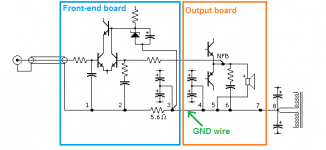
Disconnect both the "3" connections, disconnect the 4, & 6 connections.
You now have 5r6 going to 5, speaker return. This is a dedicated line that only carries the speaker return current and some very small return currents flowing in the NFB route. Oh and a tiny DC current if the voltage amplifier stage is not exactly current balanced for +ve and -ve flows. The tiny DC current cannot create any emi. You can safely ignore it. Except it confuses output offset measurements. If you compare speaker output offset to one side of the 5r6 to the measurement to the other side of 5r6 they will be different. Which is correct? Setting the net DC error to exactly zero will make the two measurements of output offset to be equal.
That arrangement keeps the "audio" side separate from the power side, no sharing of current routes.
Now connect the two 3s to 4. Connect the Zobel 6 to 4.
Connect 4 to 7
"7" has become the Main Audio Ground. It's where all the circuits resolve their currents
7 is connected as a "star of stars" (or buss if you prefer) to 8, 4, 5, 5r6 (this is the first star).
4 is connected to 3+3 & 6 (this is the second star).
Once you have corrected the sch to show the correct connections you then analyse the current loops. Find each source and the route that source uses to send current out into the load and where it comes back. Every source+current route must be arranged to have low LOOP AREA. you can "SEE" three source current routes from the input.
1.) The loop going into the coax.
2.) The loop around the RF cap and back to the coax.
3.) The loop from the RFcap/LTPbase across the LTP to the NFB lower leg R+C to "2" to "1" and up the cap back to the input base.
4.) The missing loop for the Rin resistor at the input base. This returns to the coax alongside the RF cap.
Do the same for the speaker leads.
Do the same for each decoupling capacitor, there are four decoupling capsa and each has a current route AREA that needs to be minimised.
Do the same for the Zobel current route.
Last edited:
- Status
- This old topic is closed. If you want to reopen this topic, contact a moderator using the "Report Post" button.
- Home
- Amplifiers
- Solid State
- Preventing Hum/Noise in Amplifiers