I don't like the idea with diodes in the safety connector as this is not
"the state of the art" as defined by official organizations like DIN and VDE.
And many safety testers will recognice your amp as faulty.
There are better methods used in industry for over 50 years.
Udo
"the state of the art" as defined by official organizations like DIN and VDE.
And many safety testers will recognice your amp as faulty.
There are better methods used in industry for over 50 years.
Udo
The "Safety Connector" is the PE wire directly and mechanically connected to the Chassis/Enclosure.I don't like the idea with diodes in the safety connector............many safety testers will recognice your amp as faulty................
The testing equipment will recognise this DIRECT PE connection and pass the equipment as compliant.
Could you link us/me to these better methods?..............There are better methods used in industry for over 50 years..............
The "Safety Connector" is the PE wire directly and mechanically connected to the Chassis/Enclosure.
The testing equipment will recognise this DIRECT PE connection and pass the equipment as compliant.
Any touchable metal part should be tested, including touchable connectors...
Does any one of the big hifi companies use this diode trick? And if not why?
Last edited:
Thanks
Yes - I have gone over to returning the speaker 0V to the amplifier PCB and not directly to the central ground - neater and you also get a smaller loop area. I might commrnt further on this in later updates - it will remain a 'living' document no doubt.
Hi Andrew,
Do you have measured proof that it's the better way to connect 0V speaker wire?
I tried both way with mixed result.
BR Damir
Hello Damir,
You can return the speaker 0V to either the main central ground, or return it to the PCB and from there a 0V wire that goes back to the central 0V. I have used both methods (e.g. sx and nx amps go directly back to central 0V)
In both cases, the idea is to minimize the loop area, so I recommend that if you use the latter method, you run the speaker return wire next to the speaker + wire (twist them) back to the PCB and then continue the speaker 0V wire back to central ground.
I have gone over to returning the speaker 0V back to the amplifier module 0V (which is arranged in a STAR GND) and then a single 0V line to the central ground. I have not picked up any problems and am getting no observable difference in performance. Note that on the main PCB, I have local decoupling of 2 x 220uF 100V per rail per amplifier module (4 devices per amplifier module). This is important in order to keep the loop area small.
Anyway, can you share what you have found?
Any touchable metal part should be tested, including touchable connectors...
Does any one of the big hifi companies use this diode trick? And if not why?
If you touched the mains on any part of the chassis it would trip the RCB - there is a direct connection to mains PE as AndrewT has pointed out.
If you touched mains on any connector it would trip the RCB or blow open circuit.
I have used a GL on the sx, nx and e-Amps with no problems.
Note, you must use a good quality 25/35A or better diode bridge. The ones I used on the sx and nx amp are 600V PIV and 400 Amps surge current.
If you are not comfortable using a ground lifter (GL), then my recommendation is DON'T.
I do not know of any commercial audio companies using this technique.
On page 402 of Self's APADH (3rd Edition) there is a grounding scheme with the input socket ground taken directly to the IEC connector PE.
I will look into this and then once clear about it, add it to the presentation. I tried it a few years ago but got hum - but I believe this was because of errors I made elsewhere at the time.
I will look into this and then once clear about it, add it to the presentation. I tried it a few years ago but got hum - but I believe this was because of errors I made elsewhere at the time.
Last edited:
Yes I know the diagram you mean. I had a conversation with Andrew T about that and I got thoroughly confused. Ha!
I have power supply in a separate enclosure to my power amps, in fact two separate PSU's for 4 amps, are there any special requirements to your knowledge? Thanks
I have power supply in a separate enclosure to my power amps, in fact two separate PSU's for 4 amps, are there any special requirements to your knowledge? Thanks
Last edited:
Walkalone, Join 2,3 together and place 4,6,7,8 so that their paths are very short and wide.
For best results, you should place the feedback loop parallel to the speaker without introducing any other currents within that loop.
Thanks Mark,
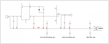
If i remember correctly, 0V of local decoupling caps is the reference for all return lines of this local circuit. As my picture, point 5 is 0V of front-end decoupling caps, it become reference point for front-end board. Point 5 is connected as series to output stage's ground. 0V of output stage's decoupling caps is the reference for all output return line, including front-end ground . All they make a series ground bus. This is reason of my grounding design. Is it correct?!
On previous time, i use old suggestion of Bonsai. Speaker and Zobel return should be routed to 0V that near main filter caps.
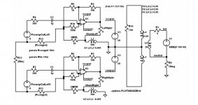
The amp reference points are 2 and 3 as that is where the two inputs are connected.
Any voltages generated within the speaker-feedback loop will force the amp to react on these. Moving these voltages out of the loop can only help. Try connecting a signal generator is series with the speaker, the amp will output an opposite signal.
Doing simulations of the capacitor currents in a class AB amp helped me understand how to arrange the connections.
"There are better methods used in industry for over 50 years."
Udo, please share these techniques - we can add them to the existing methods in use - good to discuss this.
First the obvious things:
Reduce your ground differential potential by using one plugbar (outlet).
Use short cabling and an antenna ground loop isolator.
Use separate heavy ground wire between different components to force
loop current away from sensitive inputs.
Normally this simple methods are enough to get CD quality.
If you have a large installation, use balanced I/O at least for parts.
This is an reliable method to get rid of any ground loop problems.
You can even use differential inputs with single ended inputs.
The shield is your reference input.
Due to the high input impedance of a differential input,
no ground current can flow.
The consumer industry today uses Class-II installations for 99% of the
hifi sources. Only the power amp is grounded
=> Ground loop problem solved.
Today most power supplies are switching ones with low capacitance
between windings and with non audible ripple noise
=> Big potential improvement to the toroid transformers
with their large capacitance and low frequency magnetic fields
which are difficult to shield.
Why not combine your diode hack with a partially Class-II design?
Your circuit ground and connectors could be Class-II and left floating.
And Class-II is safer, especially in the service and repair event
(no touchable parts, even if housing is open).
The grounded Class-I housing is no disadvantage.
You only need a Class-II rated transformer and additional isolation
at the touchable parts. The diodes dould be left out.
Add two fuses in the Life and Neutral line.
By having control over the fuses you can relax the diode ratings.
Anyway the diode hack needs a test protocol for each exemplar.
It has a reason that e.g. X or Y capacitors exist.
Also note that there are special requirements for isolation bridging circuit
elemens. Don't assume that a part which is not intended
and tested for safety will always work.
Udo
The amp reference points are 2 and 3 as that is where the two inputs are connected.
Any voltages generated within the speaker-feedback loop will force the amp to react on these. Moving these voltages out of the loop can only help. Try connecting a signal generator is series with the speaker, the amp will output an opposite signal.
Doing simulations of the capacitor currents in a class AB amp helped me understand how to arrange the connections.
So, it's always a good idea to use a HBR between the input and output reference points?
Yes, if you want to control ground loop currents and you don't want to use a transformer at the input or go balanced.
My opinion is that there should be a grounding standard that includes HBR and GLB. Was everyone taking a nap 50 years ago? Luckily it is not left to the audio industry to write connection protocols anymore.
My opinion is that there should be a grounding standard that includes HBR and GLB. Was everyone taking a nap 50 years ago? Luckily it is not left to the audio industry to write connection protocols anymore.
HBR is required for multi-channel amplifiers.So, it's always a good idea to use a HBR between the input and output reference points?
A monoblock does not have an input signal return LOOP, so does not need HBR to attenuate the interference current in the non existant LOOP.
A balanced impedance connection keeps the shield route and it's LOOP out of the signal route.
The amp reference points are 2 and 3 as that is where the two inputs are connected.
Any voltages generated within the speaker-feedback loop will force the amp to react on these. Moving these voltages out of the loop can only help. Try connecting a signal generator is series with the speaker, the amp will output an opposite signal.
Doing simulations of the capacitor currents in a class AB amp helped me understand how to arrange the connections.
OK, you're right, Mark.
Here is the remedy of Daniel Joffe. His paper also said same as your suggest.
Attachments
- Status
- This old topic is closed. If you want to reopen this topic, contact a moderator using the "Report Post" button.
- Home
- Amplifiers
- Solid State
- Preventing Hum/Noise in Amplifiers