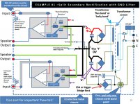
See how R9, R10, R12 and HBRL all connect to a single point. The speaker return connects first to HBR and then to power GND.
OK, but i still wonder if i have separated front-end board that request decoupling caps/regulator of it self. Where is best place to connect 0V of these decoupling caps/regulator? If it's connected between HBR and speaker return, the charge/discharge current will cause the disorder.
What does the current to the decoupling caps look like? Is the current so low that it does not matter?
Perhaps you can use rail to rail decoupling and skip the 0V connection. Or, use a second ground lead between the boards for decoupling. For Class B, what does help is connecting the Pos/Neg capacitors together and then connect to ground/0V.
Perhaps you can use rail to rail decoupling and skip the 0V connection. Or, use a second ground lead between the boards for decoupling. For Class B, what does help is connecting the Pos/Neg capacitors together and then connect to ground/0V.
Maintain the complete separation of the signal input circuit, using a two wire connection.
Then add on the separate speaker circuit again using a two wire connection.
Finally add on the FeedBack path from speaker to signal.
The first priority is to complete each and every two wire circuit connection. Only when that is complete do you then look for the missing references that relate output to input.
Dear AndrewT,
I hear that you were talking about Main Audio Ground MAG.
My knowledge about MAG as below:
1. GND input + feedback
2. 0V local decoupling caps
3. Speakers return + 0V zobel.
All joined at one point and route back to 0V main filter caps.
Is it ok? Please teach me if i wrong.
Thanks!
I hear that you were talking about Main Audio Ground MAG.
My knowledge about MAG as below:
1. GND input + feedback
2. 0V local decoupling caps
3. Speakers return + 0V zobel.
All joined at one point and route back to 0V main filter caps.
Is it ok? Please teach me if i wrong.
Thanks!
2. the 0V local decoupling caps must meet the 3. 0V Zobel Return.
The point above may not actually coincide with the MAG.
In my view the MAG can be anywhere on the line from the Local decoupling caps to the Zero Volts in the PSU output.
That line could be quite long, maybe exceeding 150mm. That leaves a lot of leaway in locating the MAG.
I prefer to locate the Input socket and Output socket fairly near each other and try to get the amp PCB to span between those two sockets, thus minimising the length of internal cabling.
Once I have acheived that, I try to local the MAG near the centroid of all those parts, i.e. input socket, PCB input, Output socket, PCB output.
I have even suggested the MAG could be located at the speaker return terminal where it enters the Chassis..
Dear Bonsai,
Your diagram as post#1 that is for common cases, supply for both output stage and front-end circuit.
If we have separate supply for front-end (often higher few Volts than supply for output stage) so, how and where to connect 0V of this separate supply to make a common ground.
Your diagram as post#1 that is for common cases, supply for both output stage and front-end circuit.
If we have separate supply for front-end (often higher few Volts than supply for output stage) so, how and where to connect 0V of this separate supply to make a common ground.
Attachments
- Status
- This old topic is closed. If you want to reopen this topic, contact a moderator using the "Report Post" button.